ENGLISH
51
Fig. J
9
40
42
41
44
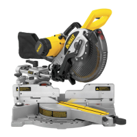
Installing a Blade (Fig. J)
1. Unplug the saw.
2. With the arm raised, the lower guard held open and the
pivot plate raised, place the blade
41
on the spindle
against the inner clamp washer
44
with the teeth at
the bottom of the blade pointing toward the back of
the saw.
3. Assemble the outer clamp washer
42
onto the spindle.
4. Install the blade screw
40
and, engaging the spindle
lock
24
, tighten the screw firmly with wrench
9
provided. (Turn counterclockwise, left-hand threads)
5. Return the guard bracket to its original position and
firmly tighten the guard bracket screw to hold bracket
in place.
WARNING:
• The guard bracket must be returned to its original
position and the screw tightened before activating
the saw.
• Failure to do so may allow the guard to contact
the spinning saw blade resulting in damage to the
saw and severe personal injury.
Adjustments
WARNING: To reduce the risk of serious personal
injury, turn off the tool and disconnect it from
the power source before attempting to move it,
change accessories or make any adjustments.
NOTE: Your miter saw is fully and accurately adjusted at
the factory at the time of manufacture. If readjustment due
to shipping and handling or any other reason is required,
follow the steps below to adjust your saw.
Once made, these adjustments should remain accurate.
Take a little time now to follow these directions carefully to
maintain the accuracy of which your saw is capable.
Checking and Adjusting the Miter Scale
(Fig. K–M)
1. Loosen the miter lock knob
5
, depress the miter detent
20
to release the miter arm. Swing the miter arm until
the latch locates it at the 0° miter position. Do not lock
miter lock knob
5
.
2. Pull down the head until the blade just enters the saw
kerf
19
.
3. Place a square
46
against the left side fence
22
and
blade
41
(Fig.K).
WARNING: Do not touch the tips of the blade teeth
with the square.
Fig. K
22
41
20
46
5
19
If adjustment is required, proceed as follows:
4. Loosen the miter lock knob (
5
, Fig. K) depress the miter
detent
20
to release the miter arm. Swing the miter
arm until the pointer points to 0° on the miter scale.
Tighten the miter lock knob
5
.
5. Loosen the left side fence clamping knob
11
and use
the wrench (
9
, Fig. M) to loosen the fence stop screw
21
. Remove the left side fence
22
.
Fig. L
11
21
22
6. Pull down the head and lock it in the lowered position
by pushing in the lock down pin. Replace the left side
fence and place a square
46
against the left side fence
and the blade. With the left side fence against the
square use the wrench
9
to tighten the hex bolts on
the fence in the order from the right side.
 Loading...