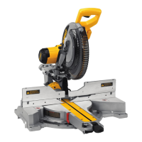
English
10
BEVEL SQUARE TO TABLE ADJUSTMENT
(FIG. 4, 6, 10)
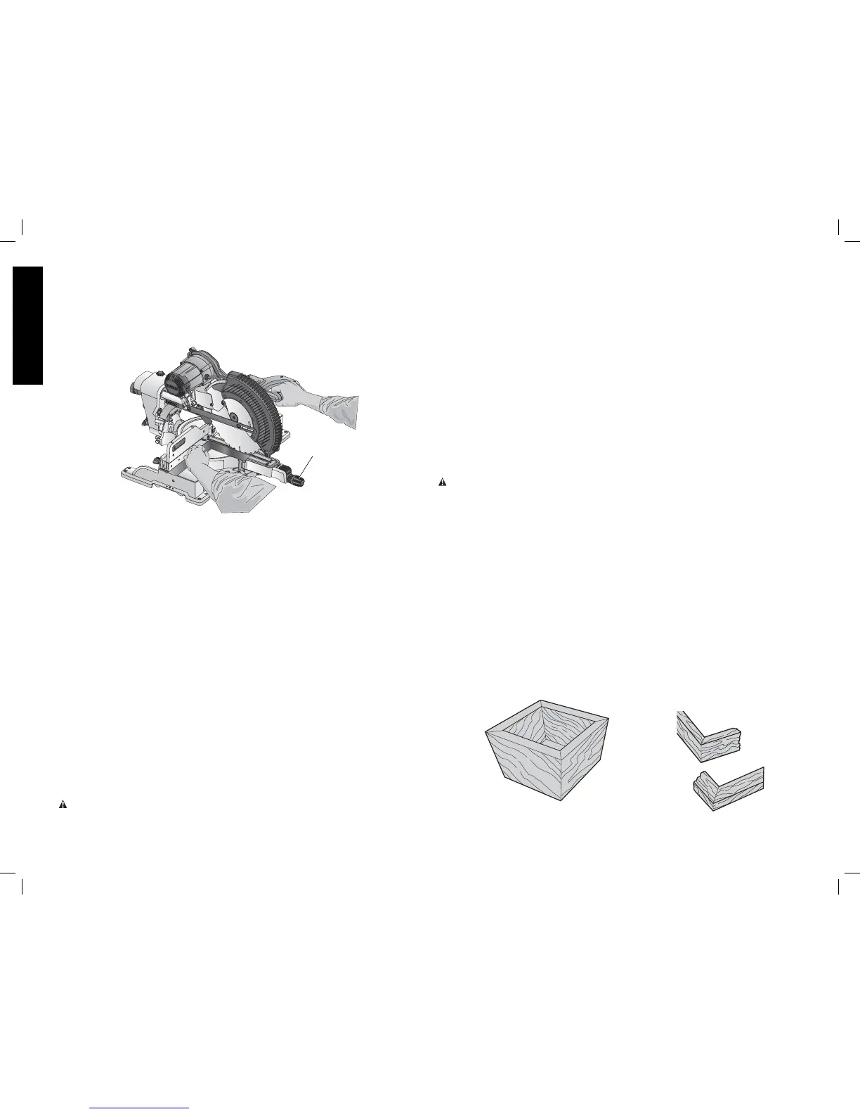
To align the blade square to the table, lock the arm in the down position with the lock down
pin. Place a square against the blade, ensuring the square is not on top of a tooth. Loosen
the bevel lock knob and ensure the arm is firmly against the 0° bevel stop. Rotate the 0° bevel
adjustment screw with the 1/2" (13 mm) blade wrench as necessary so that the blade is at 0°
bevel to the table, as measured with the square.
FIG. 10
MITER LOCK
KNOB
BEVEL POINTERS (FIG. 6)
If the bevel pointers do not indicate zero, loosen each screw that holds each bevel pointer in
place and move them as necessary. Ensure the 0° bevel is correct and the bevel pointers are
set before adjusting any other bevel angle screws.
BEVEL STOP 45º RIGHT AND LEFT ADJUSTMENT (FIG. 4, 6)
To adjust the right 45° bevel angle, loosen the bevel lock knob and pull the 0° bevel stop to
override the 0° bevel stop. When the saw is fully to the right, if the bevel pointer does not
indicate exactly 45°, turn the left 45° bevel adjustment screw with the 1/2" (13 mm) blade
wrench until the bevel pointer indicates 45°.
To adjust the left 45° bevel stop, first loosen the bevel lock knob and tilt the head to the left.
If the bevel pointer does not indicate exactly 45°, turn the right 45° bevel adjustment screw
until the bevel pointer reads 45°.
FENCE ADJUSTMENT (FIG. 4)
In order that the saw can bevel to many bevel positions, one of the fences may have to be
adjusted to provide clearance. To adjust each fence, loosen the fence adjustment knob and
slide the fence outward. Make a dry run with the saw turned off and check for clearance.
Adjust the fence to be as close to the blade as practical to provide max imum workpiece
support, without interfering with arm up and down movement. Tighten the fence adjustment
knob securely. When the bevel operations are complete, don’t forget to relocate the fence.
For certain cuts, it may be desirable to bring the fences closer to the blade. To use this feature,
back the fence adjustment knobs out two turns and move the fences closer to the blade past
the normal limit, then tighten the fence adjustment knobs to keep the fences in this location.
When using this feature, make a dry cut first to ensure the blade does not contact the fences.
NOTE: The tracks of the fences can become clogged with sawdust. If you notice that they are
becoming clogged, use a brush or some low pressure air to clear the guide grooves.
GUARD ACTUATION AND VISIBILITY (FIG. 4)
CAUTION: Pinch hazard. To reduce the risk of injury, keep thumb underneath the operating
handle when pulling the handle down. The lower guard will move up as the operating handle
is pulled down, which could cause pinching.
The lower guard on your saw has been designed to automatically uncover the blade when the
arm is brought down and to cover the blade when the arm is raised.
The guard can be raised by hand when installing or removing saw blades or for inspection
of the saw. NEVER RAISE THE LOWER GUARD MANUALLY UN LESS THE BLADE IS
STOPPED.
NOTE: Certain special cuts of large material will require that you manually raise the guard.
Refer to Cutting Large Material under Special Cuts.
The front section of the guard is louvered for visibility while cutting. Although the louvers
dramatically reduce flying debris, they are openings in the guard and safety glasses should
be worn at all times.
KERF PLATE ADJUSTMENT (FIG. 4)
To adjust the kerf plate, loosen the screws holding the kerf plate in place. Adjust so that the
kerf plate does not interfere with the blade’s movement.
RAIL GUIDE ADJUSTMENT (FIG. 4)
Periodically check the rails for any debris, play or clearance. The rails can be cleaned with a
dry clean cloth. The right rail can be adjusted with the set screw shown in Figure4. To reduce
clearance, use a 4 mm hex wrench and rotate the set screw clockwise gradually while sliding
the saw head back and forth. Reduce play while maintaining minimum slide force.
Support for Long Pieces
WARNING: To reduce the risk of injury, turn unit off and disconnect it from power
source before installing and removing accessories, before adjusting or when making
repairs. An accidental start-up can cause injury.
ALWAYS SUPPORT LONG PIECES.
Never use another person as a substitute for a table extension, as additional support for a
workpiece that is longer or wider than the basic miter saw table or to help feed, support or
pull the workpiece.
For best results, use the DW7080 extension work support to extend the table width of your
saw, available from your dealer at extra cost. Support long workpieces using any convenient
means such as sawhorses or similar devices to keep the ends from dropping.
Cutting Picture Frames, Shadow Boxes And Other Four-
Sided Projects (Fig. 11, 12)
To best understand how to make the items listed here, we suggest that you try a few simple
projects using scrap wood until you develop a “feel” for your saw.
Your saw is the perfect tool for mitering corners like the one shown in Figure 11. Sketch A in
Figure 12 shows a joint made by using the bevel adjustment to bevel the edges of the two
boards at 45º each to produce a 90º corner. For this joint the miter arm was locked in the
zero position and the bevel adjustment was locked at 45º. The wood was positioned with the
broad flat side against the table and the narrow edge against the fence. The cut could also be
made by mitering right and left with the broad surface against the fence.
FIG. 11
A
FIG. 12
B
A