English
6
On occasion, there may be a delay after trigger release to
brake engagement. On rare occasions, the brake may not
engage at all and the blade will coast to a stop.
If a delay or “skipping” occurs, turn the saw on and off 4 or 5
times. If the condition persists, have the tool serviced by an
authorized D
EWALT service center.
Always be sure the blade has stopped before removing it
from the kerf. The brake is not a substitute for guards or for
ensuring your own safety by giving the saw your complete
attention.
OPERATION
WARNING: To reduce the risk of injury, turn unit off
and disconnect it from power source before installing
and removing accessories, before adjusting or when
making repairs. An accidental start-up can cause injury.
WARNING: Always use eye protection. All users and
bystanders must wear eye protection that conforms to ANSI
Z87.1 (CAN/CSA Z94.3).
WARNING: To ensure the blade path is clear of
obstructions, always make a dry run of the cut without power
before making any cuts on the workpiece.
Plug the saw into any household 60 Hz power source.
Refer to the nameplate for voltage. Be sure the cord will not
interfere with your work.
Trigger Switch (Fig. 4)
To turn the saw on, depress the trigger switch. To turn the
tool off, release the switch. Allow the blade to spin up to full
operating speed before making the cut. Release the trigger
switch and allow the brake to stop the blade before raising
the saw head. There is no provision for locking the switch on,
but a hole is provided in the trigger for insertion of a padlock
to lock the saw off.
Cutting With Your Saw
If the slide feature is not used, ensure the saw head is
pushed back as far as possible and the rail lock knob is
tightened. This will prevent the saw from sliding along its
rails as the workpiece is engaged.
NOTE: Although this saw will cut wood and many non-
ferrous materials, we will limit our detailed discussion to the
cutting of wood only. The same guidelines apply to the
other materials. DO NOT CUT FERROUS (IRON AND
STEEL) MAT ERIALS OR MASONRY WITH THIS SAW.
Do not use any abrasive blades.
NOTE: Refer to Guard Actuation and Visibility in the
Adjustments section for important information about the
lower guard before cutting.
CROSSCUTS
A crosscut is made by cutting wood across the grain at any
angle. A straight crosscut is made with the miter arm at the
zero degree position. Set and lock the miter arm at zero, hold
MITER CONTROL (FIG. 5)
The miter lock knob and miter latch button allow you to miter
your saw to 60° right and 50° left. To miter the saw, turn
the miter lock knob counter clockwise, push the miter latch
button and set the miter angle desired on the miter scale.
Turn the miter lock knob until tight.
TRIGGER SWITCH (FIG. 4)
The trigger switch turns your saw on and off. A hole is
provided in the trigger for insertion of a padlock to secure
the saw.
BEVEL LOCK KNOB (FIG. 4)
The bevel lock allows you to bevel the saw 49° left or right.
To adjust the bevel setting, turn the knob counterclockwise.
The saw head bevels easily to the left or to the right once the
0° bevel override knob is pulled. To tighten, turn the bevel
lock knob clockwise.
0° BEVEL STOP OVERRIDE (FIG. 4, 6)
The bevel stop override allows you to bevel the saw to the
right past the 0° mark.
When engaged, the saw will automatically stop at 0° when
brought up from the left. To temporarily move past 0° to the
right, pull the bevel lock knob. Once the knob is released,
the override will be reengaged. The bevel lock knob can be
locked out by twisting the knob 180°.
When at 0°, the override locks in place. To operate the
override, bevel the saw slightly to the left.
45º BEVEL STOP OVERRIDES (FIG. 4)
The bevel stop overrides are held secure with their attachment
screw to prevent inadvertent movement. Use the bit on the
blade wrench to loosen the attachment screw. This allows
the slides, to be pulled outward and the saw head to pivot
past the 45º mark. Be sure to retighten the attachment screw
when finished.
RAIL LOCK KNOB (FIG. 4)
The rail lock knob allows you to lock the saw head firmly
to keep it from sliding on the rails. This is necessary when
making certain cuts or when transporting the saw.
LOCK DOWN PIN (FIG. 4)
WARNING: The lock down pin should be used ONLY
when carrying or storing the saw. NEVER use the lock down
pin for any cutting operation.
To lock the saw head in the down position, push the saw
head down, push the lock down pin in and release the saw
head. This will hold the saw head safely down for moving
the saw from place to place. To release, press the saw head
down and pull the pin out.
AUTOMATIC ELECTRIC BRAKE
Your saw is equipped with an automatic electric blade
brake which stops the saw blade within 5 seconds of trigger
release. This is not adjustable.
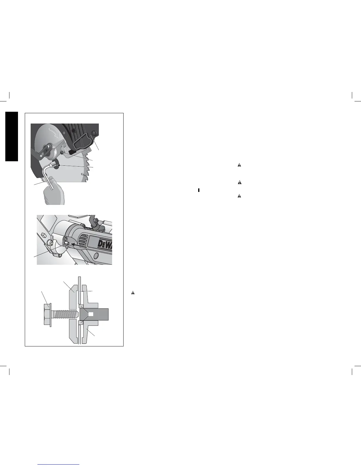
C
FIG. 3
A
B
E
D
H
G
F
E
I