11
ENGLISH
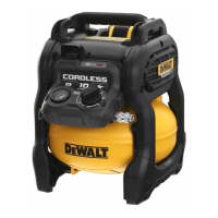
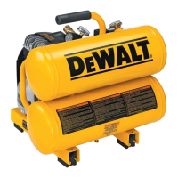
Know Your Air Compressor
READ THIS OWNER’S MANUAL AND SAFETY RULES BEFORE
OPERATING YOUR UNIT. Compare the illustrations with your unit
to familiarise yourself with the location of various controls and
adjustments. Save this manual for futurereference.
Description of Operation (Fig.A)
Become familiar with these controls before operating theunit.
Auto On(I)/Off(O) Switch
1
: Place this switch in the "AutoOn"
position to provide automatic power to the pressure switch and
"Off" to remove power at the end of eachuse.
Pressure Switch (not shown): The pressure switch
automatically starts the motor when the air tank pressure drops
below the factory set "cut-in" pressure. It stops the motor when
the air tank pressure reaches the factory set "cut-out"pressure.
Safety Valve
4
: If the pressure switch does not shut off the
air compressor at its "cut-out" pressure setting, the safety
valve will protect against high pressure by "popping out" at its
factory set pressure (slightly higher than the pressure switch
"cut-out"setting).
Tank Pressure Gauge
5
: The tank pressure gauge indicates
the reserve air pressure in thetank.
One-Turn Regulator
6
: Controls the air pressure available at
the quick-connect outlet. Turn the One-Turn regulator clockwise
to increase pressure or anti-clockwise to decrease pressure. Stop
when indicator matches with desired outlet pressure.
Cooling System (not shown): This compressor contains an
advanced design cooling system. At the heart of this cooling
system is an engineered fan. It is perfectly normal for this fan to
blow air through the vent holes in large amounts. You know that
the cooling system is working when air is beingexpelled.
Air Compressor Pump (not shown): Compresses air into the
air tank. Working air is not available until the compressor has
raised the air tank pressure above that required at the airoutlet.
Drain Valve
7
: The drain valve is located at the base of the air
tank and is used to drain condensation at the end of eachuse.
Check Valve
8
: When the air compressor is operating, the
check valve is "open", allowing compressed air to enter the air
tank. When the air compressor reaches "cut-out" pressure, the
check valve "closes", allowing air pressure to remain inside the
airtank. NOTE: The check valve has a smal opening to expel
excess air from the pump. A small amount of air releasing is
normal and does not cause any reduction in tank pressure.
Motor Overload Protector (not shown): The motor has
a thermal overload protector. If the motor overheats for any
reason, the overload protector will shut off the motor. The motor
must be allowed to cool down before restarting. Torestart:
1. Set the Auto On/Off switch to"Off".
2. Remove thebattery.
3. Allow the motor tocool.
4. Replace thebattery.
5. Set the Auto On/Off switch to "Auto On"position.
Quick-Connect Coupler
9
: The Universal EU 1/4" quick
coupling body accepts industrial Push-to-Connectplugs.
OPERATION
Instructions for Use
WARNING: Always observe the safety instructions and
applicableregulations.
WARNING: To reduce the risk of serious personal
injury, turn tool off and disconnect battery pack
before making any adjustments or removing/
installing attachments or accessories. An accidental
start‑up can causeinjury.
Inserting and Removing the Battery Pack
from the Tool (Fig.B)
NOTE: Make sure your battery pack
2
is fullycharged.
To Install the Battery Pack into the Tool Handle
1. Align the battery pack with the rails inside the tool’s
handle(Fig. B).
2. Slide it into the handle until the battery pack is firmly seated
in the tool and ensure that you hear the lock snap intoplace.
To Remove the Battery Pack from the Tool
1. Press the battery release button
3
and firmly pull the
battery pack out of the toolhandle.
2. Insert battery pack into the charger as described in the
charger section of thismanual.
Fuel Gauge Battery Packs (Fig.B)
Some DeWALT battery packs include a fuel gauge which consists
of three green LED lights that indicate the level of charge
remaining in the batterypack.
To actuate the fuel gauge, press and hold the fuel gauge
button
13
. A combination of the three green LED lights will
illuminate designating the level of charge left. When the level of
charge in the battery is below the usable limit, the fuel gauge
will not illuminate and the battery will need to berecharged.
NOTE: The fuel gauge is only an indication of the charge left on
the battery pack. It does not indicate tool functionality and is
subject to variation based on product components, temperature
and end-userapplication.
ASSEMBLY AND ADJUSTMENTS
WARNING: To reduce the risk of serious personal
injury, turn tool off and disconnect battery pack
before making any adjustments or removing/
installing attachments or accessories. An accidental
start‑up can causeinjury.
WARNING: Use only DeWALT battery packs andchargers.
The air compressor should only be carried by the handle
10
and should not be held during operation.
Moving the Compressor (Fig.E)
WARNING: To reduce the risk of serious personal
injury, ALWAYS hold securely in anticipation of a
suddenreaction.
 Loading...