33
ENGLISH
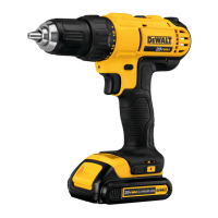
Inserting and Removing the Battery Pack
from the Tool (Fig.B)
NOTE: Make sure your battery pack
8
is fullycharged.
To Install the Battery Pack into the Tool Handle
1. Align the battery pack
8
with the rails inside the tool’s
handle (Fig. B).
ASSEMBLY AND ADJUSTMENTS
WARNING: To reduce the risk of serious personal
injury, turn tool off and disconnect battery pack
before making any adjustments or removing/
installing attachments or accessories. An accidental
start‑up can causeinjury.
WARNING: Use only
T battery packs andchargers.
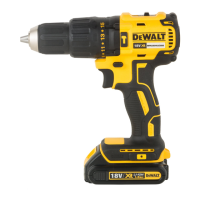
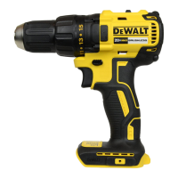
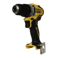
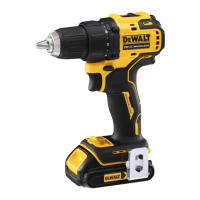
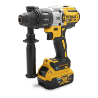
Description (Fig. A)
WARNING: Never modify the power tool or any part of it.
Damage or personal injury couldresult.
Components
1
Trigger switch
2
Forward/reverse control button
3
Torque adjustment collar
4
Gear shifter
5
Worklight
6
Keyless chuck
7
Chuck sleeve
8
Battery pack
9
Battery release button
10
Main handle
Intended Use
These drills/drivers/hammerdrills are designed for professional
drilling, percussion drilling and screwdrivingapplications.
DO NOT use under wet conditions or in the presence of
flammable liquids orgases.
These drills/drivers/hammerdrills are professional powertools.
DO NOT let children come into contact with the tool.
Supervision is required when inexperienced operators use
thistool.
• Young children and the infirm. This appliance is not
intended for use by young children or infirm persons
withoutsupervision.
• This product is not intended for use by persons (including
children) suffering from diminished physical, sensory or
mental abilities; lack of experience, knowledge or skills
unless they are supervised by a person responsible for their
safety. Children should never be left alone with thisproduct.
Date Code Position (Fig.A)
The date code
11
, which also includes the year of manufacture,
is printed into thehousing.
Example:
2020XX XX
Year and week of Manufacture
Torque Adjustment Collar (Fig.A)
Your tool has an adjustable torque screwdriver mechanism for
driving and removing a wide array of fastener shapes and sizes
and in some models, a hammer mechanism for drilling into
masonry. Circling the collar
3
are numbers, a drill bit symbol,
and on some models, a hammer symbol. These numbers are
used to set the clutch to deliver a torque range. The higher the
number on the collar, the higher the torque and the larger the
fastener which can be driven. To select any of the numbers,
rotate until the desired number aligns with thearrow.
Forward/Reverse Control Button (Fig.A)
A forward/reverse control button
2
determines the direction of
the tool and also serves as a lock‑offbutton.
To select forward rotation, release the trigger switch and depress
the for ward/re verse control button on the right side of thetool.
To select reverse, release the trigger switch and depress the
forward/reverse control button on the left side of thetool.
The center position of the control button locks the tool in the off
position. When changing the position of the control button, be
sure the trigger isreleased.
NOTE: The first time the tool is run after changing the direction
of rotation, you may hear a click on start up. This is normal and
does not indicate aproblem.
Variable Speed Trigger Switch (Fig.A)
To turn the tool on, squeeze the variable speed trigger
switch
1
. To turn the tool off, release the trigger switch. Your
tool is equipped with a brake. The chuck will stop as soon as the
trigger switch is fullyreleased.
NOTE: Continuous use in variable speed range is not
recommended. It may damage the switch and should
beavoided.
2. Slide it into the handle until the battery pack is firmly seated
in the tool and ensure that you hear the lock snap intoplace.
To Remove the Battery Pack from the Tool
1. Press the release button
9
and firmly pull the battery pack
out of the toolhandle.
2. Insert battery pack into the charger as described in the
charger section of thismanual.
Fuel Gauge Battery Packs (Fig.A)
Some
battery packs include a fuel gauge which consists
of three green LED lights that indicate the level of charge
remaining in the batterypack.
To actuate the fuel gauge
12
, press and hold the fuel gauge
button. A combination of the three green LED lights will
illuminate designating the level of charge left. When the level of
charge in the battery is below the usable limit, the fuel gauge
will not illuminate and the battery will need to berecharged.
NOTE: The fuel gauge is only an indication of the charge left on
the battery pack. It does not indicate tool functionality and is
subject to variation based on product components, temperature
and end‑userapplication.
 Loading...