57
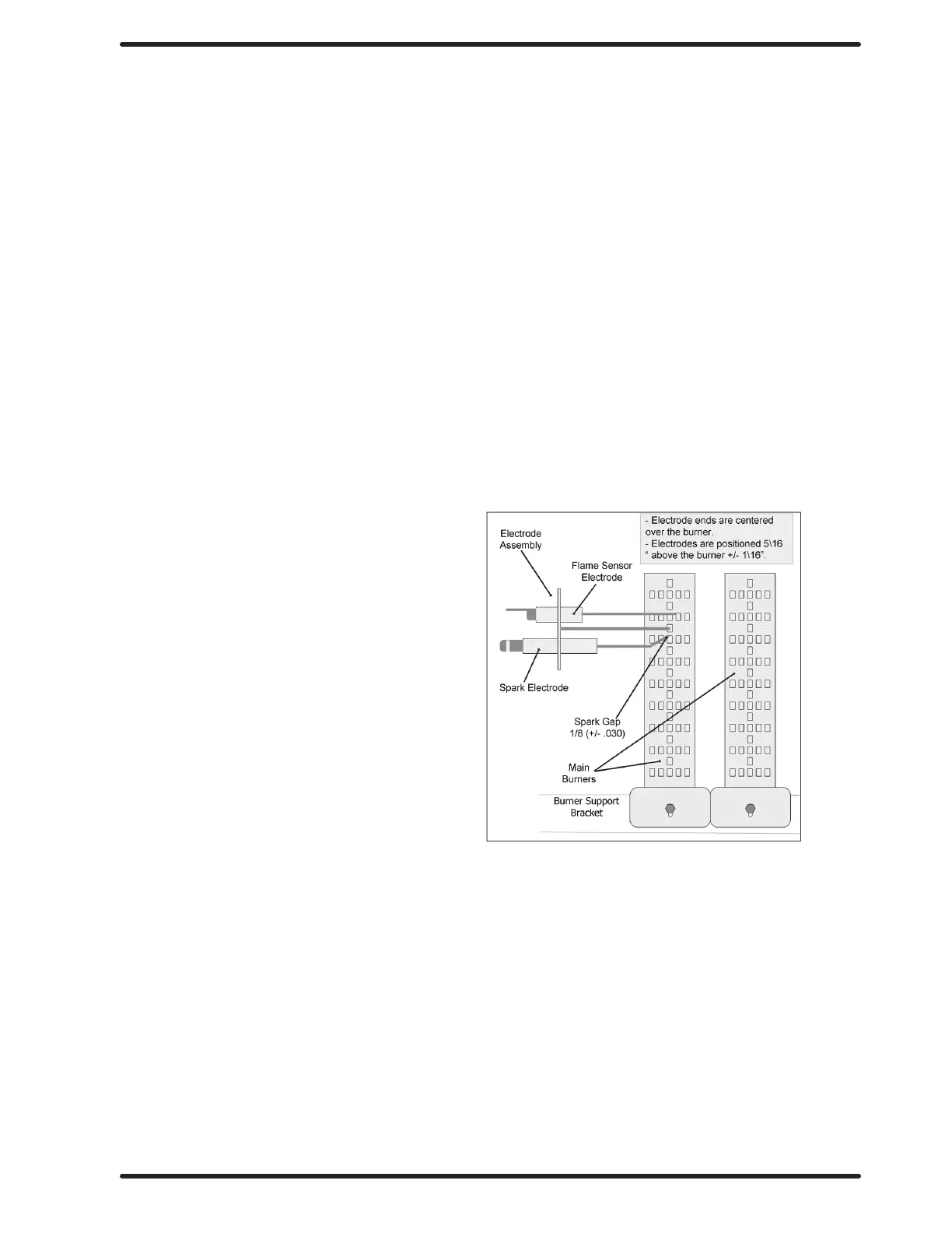
Spark Electrode Assembly-Function
Step 1: The spark electrode and sensing electrodes are located directly at the side of
the burner housing.
Step 2: The electrode with the black hi-voltage wire conducts the spark to the center
grounding probe, directly over the burner.
Step 3: The electrode with the black sensing wire detects ignition and monitors ame
by signaling the module.
NOTE: Proper grounding of the ignition system (yellow wires) is very critical for
proper ignition sequence.
Ignition System-Function & Sequence
During normal dryer operation, the following occurs:
1. The dryer electronic control calls for heat.
2. From the 24VAC control transformer, voltage for the heat circuit is applied to the control through the
door switch. If the control detects that the heat should be on, a circuit is closed providing power through
the over-temp thermostat, the air damper switch, the high limit switch and the motor centrifugal
switch to the Ignition Module.
3. Once the 24VAC reaches the ignition
module on the red, sparking occurs at
the ignition electrode and 24VAC
is applied to open the Gas Valve.
3. Once the ame is established,
the sensing electrode detects
the presence of ame and the
sparking stops.
4. If for any reason the ame
is not established in a period of 10
seconds, the electronic control will try
this sequence for 3 tries. Normally the
10 seconds “Trial For Ignition” period is
ample to establish and prove ame.
5. If the ame is shutdown or blown out
during operation, the ignitor will
immediately go into “Trial. For Ignition”
again for 10 seconds.
6. However,at the end of 3 separate retries of 10 seconds “Trial for Ignition”, the ame is not established,
the ignition system goes into “Safety Lock-Out” and will not reactivate the “Trial for Ignition” until there is
a current interruption for a period of 15 seconds. This interruption can be provided by opening the
dryer loading door and allowing the machine to come to a complete stop for 15 seconds.
Part # 8533-112-001 7/21
 Loading...