EasyManua.ls Logo

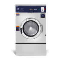
Dexter Laundry T600 User Manual

Dexter Laundry T600
98 pages
To Next Page IconTo Next Page
Page #1 background imageLoading...
Page #1 background image
PLEASE USE THE TABS LOCATED ON THE
RIGHT AND LEFT SIDES OF THE DOCUMENT
TO ADVANCE TO EACH SECTION.
8533-072-001 3/22

Table of Contents

Other manuals for Dexter Laundry T600

Questions and Answers:

Dexter Laundry T600 Specifications

General IconGeneral
ModelT600
TypeFront Load Washer
Capacity20 lb (9.1 kg)
Control TypeMicroprocessor
Phase3
Width27.5 in
Depth32.13" (816 mm)

Summary

Equipment Safety Warnings Symbols and Terminology

DANGER Symbol and Meaning

Indicates imminent hazard resulting in death or serious injury.

WARNING Symbol and Meaning

Indicates potential hazard resulting in death or serious injury.

Electrical Hazard Symbol

Symbol indicating dangerous high voltages present inside product.

Prohibited and Mandatory Actions

Prohibited: Do Not Enter Equipment or Space

Prohibits entry into the equipment or its space.

Prohibited: Do Not Step or Stand on Equipment

Prohibits stepping or standing on the equipment.

Prohibited: Do Not Operate Without Guards

Prohibits operation without all guards and covers in place.

Prohibited: Do Not Wash Flammable Liquids

Prohibits washing clothing with flammable liquids (petrochemicals).

Prohibited: Do Not Allow Children to Play

Prohibits children from playing in or around the equipment.

Mandatory: Disconnect Power Before Servicing

Disconnect power before performing any servicing on the equipment.

Mandatory: Lock Out/Tag Out Before Servicing

Implement lock out/tag out procedures before servicing the equipment.

Mandatory: Disconnect Water Supply Before Servicing

Disconnect water supply before commencing any servicing activities.

General Safety Precautions

WARNING: Installation Codes

Washers must be installed according to local electrical and plumbing codes.

WARNING: Children Supervision

Children should be supervised to ensure they do not operate or play.

Keep Panels in Place

Keep all panels in place to protect against shock and injury.

Appliance Use Restrictions

Appliance not for persons with reduced capabilities unless supervised.

Dexter Safety Guidelines

Always Shut Off Power and Water

Always shut off power and water supply before servicing.

Do Not Use Volatile Substances

Do not use volatile or flammable substances in or near the washer.

Section 2: Machine Installation & Operating Instructions

Foundation Requirements

Specifies requirements for a substantial concrete floor or suitable base for installation.

Electrical

Discusses permanent installation, branch circuits, and conduit requirements.

Electrical Connections

Fuse Requirements

Lists dual element time delay fuse or equivalent breaker amperage requirements.

Emergency Stop / Safety Door Lock

Details the operation of the emergency stop button and safety door lock feature.

Operating Instructions

Starting the Washer

Steps for loading clothes, adding detergent, and selecting temperature.

Section 3: Machine Programming Instructions

Programming Instructions

Explains manual programming via machine controls or PDA.

Coin Price Programming

Details the seven stages for setting coin prices and values.

Programming Instructions Details

Wash Cycle Programming

Steps for changing wash cycle parameters like baths, times, and temperatures.

Section 4: Trouble Shooting

Common Troubleshooting Solutions Pages

Pages providing solutions for common washer issues and fault codes.

Troubleshooting Machine Fault

Guide to troubleshooting specific machine faults displayed on the front.

Errors Pages

Section detailing error codes and their corresponding customer actions.

Main Control Printed Circuit Board Procedures

Remove Power and Lockout Safely

Procedure to safely remove power and lock out the machine before working on the PCB.

CAUTION: Do Not Soft Reset

Warning against soft resetting when installing a new battery to avoid programming issues.

Common Troubleshooting Solutions

Troubleshooting Machine Fault Errors

Fault F1: Door Failed to Close/Lock

Describes fault F1 and customer actions for door lock issues.

Fault F2: Washer Tub Does Not Fill

Describes fault F2 and customer actions for washer tub fill problems.

Fault F3: Memory Error in Controller

Describes fault F3 and customer actions for controller memory errors.

Fault F4: Washer Controller Communication Error

Describes fault F4 and customer actions for communication errors.

Fault F5: Pressure Switch Error

Describes fault F5 and customer actions for pressure switch errors.

Fault F6: Wrong Washer Size for Drive Type

Describes fault F6 and customer actions for incorrect drive size settings.

Fault F7: Wrong Size Drive Installed

Describes fault F7 and customer actions for incorrect drive size installation.

Fault F8: Washer Tub Does Not Empty

Describes fault F8 and customer actions for tub emptying issues.

Fault F9: Washer Does Not Reach Spin Target Frequency

Describes fault F9 and customer actions for spin speed frequency issues.

Fault F10: After Spin, Washer Tub Does Not Stop

Describes fault F10 and customer actions for tub not stopping after spin.

Fault F11: Drive Size Setting Has Changed

Describes fault F11 and customer actions for changed drive size settings.

Fault F12: Washer Controller Internal Error

Describes fault F12 and customer actions for internal controller errors.

Troubleshooting Machine Fault Errors (Continued)

Fault F13: VFD and Washer Computer Not Communicating

Describes fault F13 and customer actions for VFD communication issues.

Fault F22: MS300 Drive Conversion Only

Describes fault F22 for MS300 drive conversion.

Fault F14: Over-current on the Drive or Motor

Describes fault F14 and customer actions for over-current issues.

Fault F23: VFD Replacement/Disconnection

Describes fault F23 related to VFD replacement or disconnection.

Fault F15: Variable Frequency Drive Senses High Internal Voltage

Describes fault F15 and customer actions for high internal voltage issues.

Fault F24: Injection Relay PCB Issues

Describes fault F24 related to injection relay PCB addition or connection.

Fault F16: Temperature Sensor Detects High Internal Temperature

Describes fault F16 and customer actions for high temperature sensor readings.

Fault F25: Water Valve PCB Replacement

Describes fault F25 related to water valve PCB replacement.

Fault F17: Overload of the Drive or Motor

Describes fault F17 and customer actions for drive or motor overload.

Fault F26: VFD Unit Addition/Connection

Describes fault F26 related to VFD unit addition or connection.

Fault F18: Ground Fault to the Drive

Describes fault F18 and customer actions for ground faults to the drive.

Fault F27: Injection Relay PCB Addition

Describes fault F27 related to injection relay PCB addition.

Fault F19: Low Voltage to the Drive

Describes fault F19 and customer actions for low voltage to the drive.

Fault F28: Water Valve PCB Addition

Describes fault F28 related to water valve PCB addition.

Fault F20: Internal Drive Error

Describes fault F20 and customer actions for internal drive errors.

Fault F21: Data Error on Communications Between Controller and Drive

Describes fault F21 and customer actions for data communication errors.

Section 5: Machine Service Procedures

Service Procedures (Continued)

Adjusting the Loading Door

Guidance on adjusting the loading door fit and pressure.

Drive Motor Removal

Step-by-step instructions for removing the drive motor from the machine.

Door Lock Assembly Operation

Details the operation of the door lock mechanism and its switches.

Service Procedures (Continued)

Tub Back, Bearing and Cylinder Assembly

Instructions for removal and reassembly of the tub back, bearing, and cylinder.

Basket Pulley, Bearing Housing, Water Seals and Tub back

Details removal and reassembly of the basket pulley assembly.

Removal of Bearing Housing From Basket Shaft, Bearings and Water Seals

Steps for removing the bearing housing from the basket shaft.

Reinstallation onto Basket Shaft

Procedures for reinstalling the assembly onto the basket shaft.

Section 6: Service Electrical Components

Circuit Breaker/Fuse

Location and reset/replacement instructions for circuit breakers and fuses.

Electrical Components (Continued)

Pressure Switch Caution

Caution regarding changing pressure switch adjustment and its effect on water usage.

Emergency Stop Button Switch Assembly

Instructions for removing the emergency stop button switch assembly.

Delta Variable Frequency Drive

Explains power connection to the Delta drive for three-phase or single-phase sources.

Delta VFD Dynamic Braking Resistors

Description of dynamic braking resistors and safety precautions.

Section 7: Electrical Wiring Diagrams & Schematics

Start Circuit

Details the power flow and connections for the machine's start circuit.

Fill Circuit-Warm

Explains the fill circuit, including water valves and thermoactuator operation.

Wash Circuit

Describes the wash circuit, including tub filling and basket tumbling.

Drain

Explains the drain circuit, how the valve opens, and pressure switch reset.

Rinse 1 & 2

Describes the Rinse 1 & 2 circuits, including fill, tumble, and temperature settings.

Electrical Schematics (Continued)

Trouble Shooting

Machine Does Not Start

Troubleshooting steps for machine power supply, door switch, breaker, transformer, and coin acceptor.

Machine Will Not Accept and Count Coins

Steps to troubleshoot coin acceptor issues including PCB, wiring, and breaker.

Door Does Not Lock

Troubleshooting for door lock issues, checking display, solenoid, switch, and thermoactuator.

Door Will Not Open

Procedures to follow if the door fails to open after the cycle.

Parts Data (Continued)

Section 9: Coin Handling Parts

Coin Micro Switch 20Lb. Non-Express: 120 Volt

20lb Non-Express: U.S. Optical Acceptor

20lb Non-Express: Electronic Acceptor

20lb Non-Express: Electronic Acceptor (208-240V)

20lb Non-Express: U.S Optical Acceptor (208-240V)

20lb Express: Electronic Acceptor (208-240V)

20lb Express: Micro Switch Acceptor (208-240V)

30Lb. Express: Non-Express Electronic Acceptor

30Lb. Express: Non-Express Electronic Acceptor (208-240V)

40Lb. Non-Express: Coin Micro Switch

40lb Non-Express: U.S. Optical Acceptor

EasyCard Interface Schematics & Diagrams

50Hz Model Parts (Continued)

Section 12: Maintenance