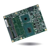
www.dfi .comChapter 3 Hardware Installation
22
Chapter 3
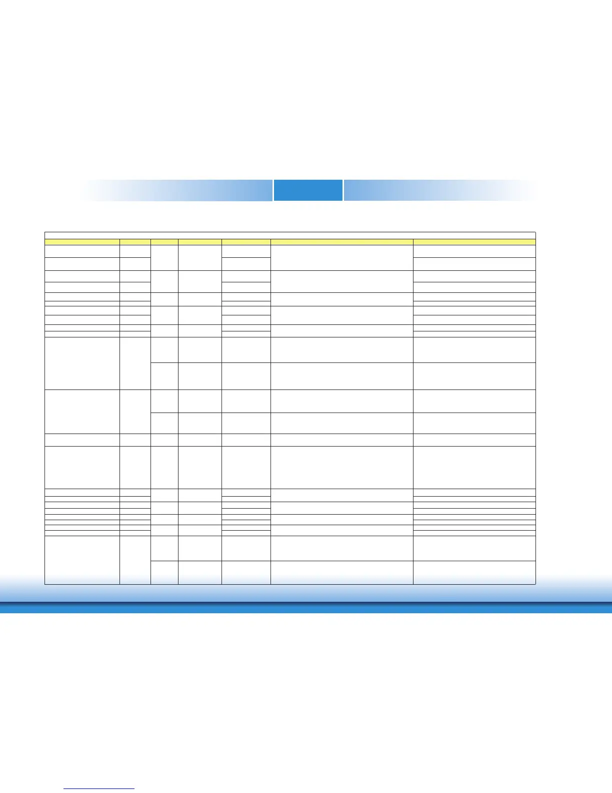
DDI1_PAIR2+ D32 DP1_LANE2+ for DP / TMDS1_DATA0+ for HDMI or DVI
DDI1_PAIR2- D33 DP1_LANE2- for DP / TMDS1_DATA0- for HDMI or DVI
DDI1_PAIR3+ D36 DP1_LANE3+ for DP / TMDS1_CLK+
DDI1_PAIR3- D37 DP1_LANE3- for DP / TMDS1_CLK-
DDI1_PAIR4+ C25 NA,no spport NA
DDI1_PAIR4- C26 NA,no spport NA
DDI1_PAIR5+ C29 NA,no spport NA
DDI1_PAIR5- C30 NA,no spport NA
DDI1_PAIR6+ C15 NA,no spport NA
DDI1_PAIR6- C16 NA,no spport NA
I/O PCIE AC coupled on Module
PD 100K to GND
(S/W IC between
Rpu/PCH)
DDI for Display Port: DP1_AUX+ Differetial pairs
(DP AUX+ function if DDI1_DDC_AUX_SEL is no connect)
Half-duplex bi-directional AUX channel for services such as link
configuration or maintenance and EDID access
DP1_AUX+ for DP
I/O OD CMOS 3.3V / 3.3V
PU 2.2K to 3.3V, PD 100K
to GND
(S/W IC between
Rpu/Rpd resistor)
DDI for SDVO: SDVO1_CTRLCLK (SDVO I2C clock line - to set up SDVO
peripherals.)
DDI for HDMI/DVI: HDMI1_CTRLCLK
(HDMI/DVI I2C CTRLCLK if DDI1_DDC_AUX_SEL is pulled high)
HDMI1_CTRLCLK for HDMI or DVI
I/O PCIE AC coupled on Module
PU 100K to 3.3V
(S/W IC between
Rpu/PCH)
DDI for Display Port: DP1_AUX- Differetial pairs
(DP AUX- function if DDI1_DDC_AUX_SEL is no connect)
Half-duplex bi-directional AUX channel for services such as link
configuration or maintenance and EDID access
DP1_AUX- for DP
I/O OD CMOS 3.3V / 3.3V
PU 2.2K to 3.3V/PU 100K
to 3.3V
(S/W IC between
2.2K/100K resistor)
DDI for SDVO: SDVO1_CTRLDATA (SDVO I2C data line - to set up SDVO
peripherals.)
DDI for HDMI/DVI: HDMI1_CTRLDATA
(HDMI/DVI I2C CTRLDATA if DDI1_DDC_AUX_SEL is pulled high)
HDMI1_CTRLDATA for HDMI or DVI
DDI1_HPD C24 I CMOS 3.3V / 3.3V PD 1M to GND
DDI for Display Port: DP1_HPD (DP Hot-Plug Detect)
DDI for HDMI/DVI: HDMI1_HPD (HDMI Hot-Plug Detect)
DP1_HPD for DP / HDMI1_HPD for HDMI or DVI
DDI1_DDC_AUX_SEL D34 I CMOS 3.3V / 3.3V PD 1M to GND
Selects the function of DDI1_CTRLCLK_AUX+ and
DDI1_CTRLDATA_AUX-. This pin shall have a 1M pull-down to
logic ground on the Module. If this input is floating the AUX pair is
used for the DP AUX+/- signals. If pulled-high the AUX pair contains the
CRTLCLK and CTRLDATA signals.
Selects the function of DP1 AUXƲ(Low) or HDMI1 DDC
CLK/DATA(High)
The DDC_AUX_SEL pin should be routed to pin 13 of the
DisplayPort connector, to enable Dual-Mode.
When HDMI/DVI is directly done on the Carrier Board, this pin
shall be pulled to 3.3V with a 100k Ohm resistor to configure the
AUX pairs as DDC channels.
DDI2_PAIR0+ D39 DP2_LANE0+ for DP / TMDS2_DATA2+ for HDMI or DVI
DDI2_PAIR0- D40 DP2_LANE0- for DP / TMDS2_DATA2- for HDMI or DVI
DDI2_PAIR1+ D42 DP2_LANE1+ for DP / TMDS2_DATA1+ for HDMI or DVI
DDI2_PAIR1- D43 DP2_LANE1- for DP / TMDS2_DATA1- for HDMI or DVI
DDI2_PAIR2+ D46 DP2_LANE2+ for DP / TMDS2_DATA0+ for HDMI or DVI
DDI2_PAIR2- D47 DP2_LANE2- for DP / TMDS2_DATA0- for HDMI or DVI
DDI2_PAIR3+ D49 DP2_LANE3+ for DP / TMDS2_CLK+
DDI2_PAIR3- D50 DP2_LANE3- for DP / TMDS2_CLK-
I/O PCIE AC coupled on Module
PD 100K to GND
(S/W IC between
Rpu/PCH)
DDI for Display Port: DP2_AUX+ Differetial pairs
(DP AUX+ function if DDI2_DDC_AUX_SEL is no connect)
Half-duplex bi-directional AUX channel for services such as link
configuration or maintenance and EDID access
DP2_AUX+ for DP
I/O OD CMOS 3.3V / 3.3V
PU 2.2K to 3.3V, PD 100K
to GND
(S/W IC between
Rpu/Rpd resistor)
DDI for HDMI/DVI: HDMI2_CTRLCLK
(HDMI/DVI I2C CTRLCLK if DDI2_DDC_AUX_SEL is pulled high)
HDMI2_CTRLCLK for HDMI or DVI
I PCIE
O PCIE AC coupled off Module
DDI for Display Port: DP2_LANE 2 differential pairs
DDI for HDMI/DVI: TMDS2_DATA lanes 0 differential pairs
O PCIE AC coupled off Module
AC coupled off Module
DDI for SDVO: SDVO1_FLDSTALL± differential pair
(Serial Digital Video Field Stall input differential pair.)
O PCIE
O PCIE AC coupled off Module
I PCIE
I PCIE AC coupled off Module
DDI for SDVO: SDVO1_TVCLKIN± differential pair
(Serial Digital Video TVOUT synchronization clock input differential pair.)
AC coupled off Module
DDI for Display Port: DP2_LANE 1 differential pairs
DDI for HDMI/DVI: TMDS2_DATA lanes 1 differential pairs
DDI for Display Port: DP2_LANE 3 differential pairs
DDI for HDMI/DVI: TMDS2_CLK differential pairs
DDI1_CTRLCLK_AUX+ D15
DDI1_CTRLDATA_AUX- D16
DDI2_CTRLCLK_AUX+ C32
DDI for Display Port: DP2_LANE 0 differential pairs
DDI for HDMI/DVI: TMDS2_DATA lanes 2 differential pairs
AC coupled off Module
DDI for SDVO: SDVO1_INT± differential pair
(Serial Digital Video B interrupt input differential pair)
O PCIE AC coupled off Module
O PCIE AC coupled off Module
DDI for Display Port: DP1_LANE 2 differential pairs
DDI for SDVO: SDVO1_BLU± differential pair (Serial Digital Video blue
output)
DDI for HDMI/DVI: TMDS1_DATA lanes 0 differential pairs
DDI for Display Port: DP1_LANE 3 differential pairs
DDI for SDVO: SDVO1_CK± differential pair (Serial Digital Video clock
output)
DDI for HDMI/DVI: TMDS1_CLK differential pairs
Signal Pin# Pin Type Pwr Rail /Tolerance CH960 PU/PD Module Base Specification R2.1 Description COM Express Carrier Design Guide R2.0 Description
DDI Si
 Loading...