www.dfi .comChapter 3 Hardware Installation
23
Chapter 3
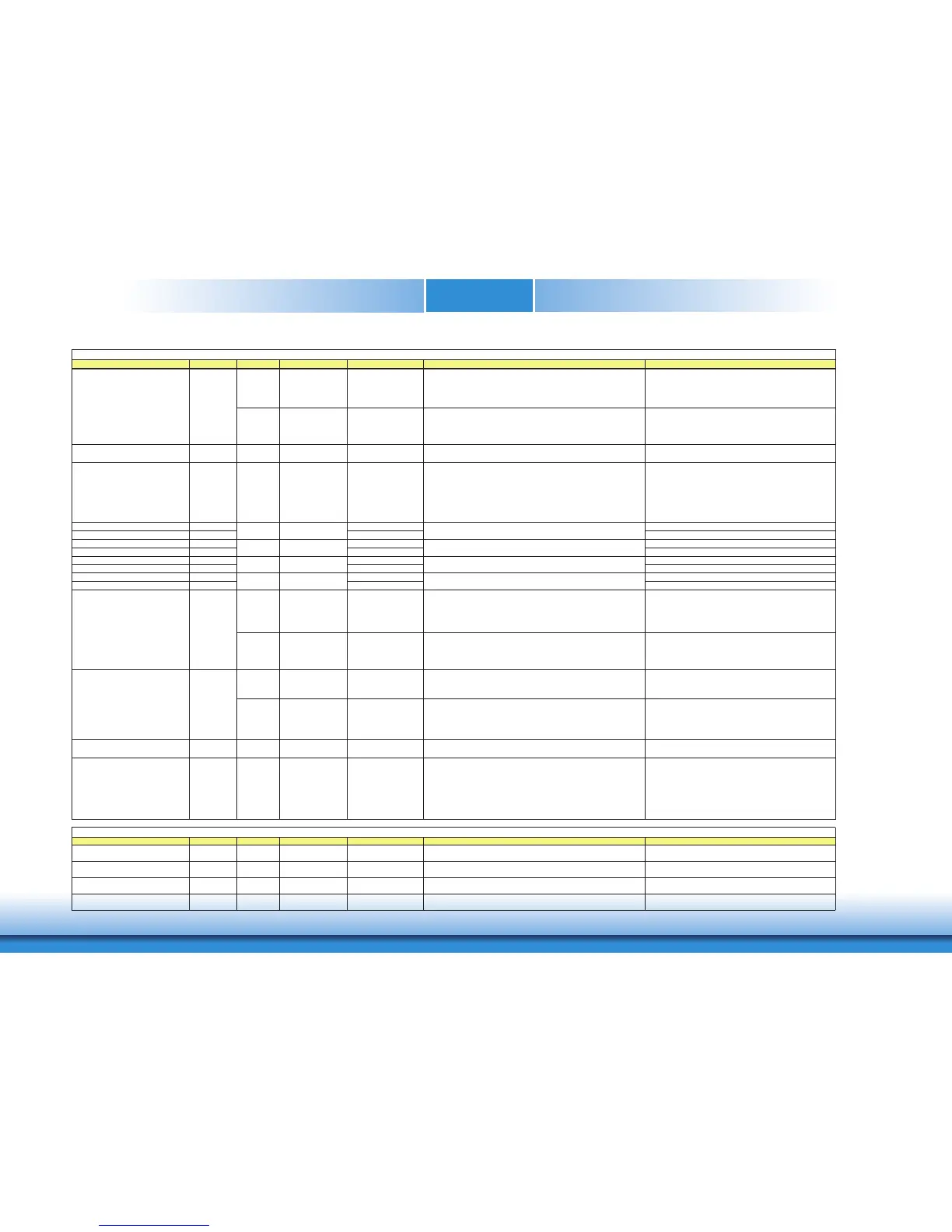
I/O PCIE AC coupled on Module
PU 100K to 3.3V
(S/W IC between
Rpu/PCH)
DDI for Display Port: DP2_AUX- Differetial pairs
(DP AUX- function if DDI2_DDC_AUX_SEL is no connect)
Half-duplex bi-directional AUX channel for services such as link
configuration or maintenance and EDID access
DP2_AUX- for DP
I/O OD CMOS 3.3V / 3.3V
PU 2.2K to 3.3V/PU 100K
to 3.3V
(S/W IC between
2.2K/100K resistor)
DDI for HDMI/DVI: HDMI2_CTRLDATA
(HDMI/DVI I2C CTRLDATA if DDI2_DDC_AUX_SEL is pulled high)
HDMI2_CTRLDATA for HDMI or DVI
DDI2_HPD D44 I CMOS 3.3V / 3.3V PD 1M to GND
DDI for Display Port: DP2_HPD (DP Hot-Plug Detect)
DDI for HDMI/DVI: HDMI2_HPD (HDMI Hot-Plug Detect)
DP2_HPD for DP / HDMI1_HPD for HDMI or DVI
DDI2_DDC_AUX_SEL C34 I CMOS 3.3V / 3.3V PD 1M to GND
Selects the function of DDI2_CTRLCLK_AUX+ and
DDI2_CTRLDATA_AUX-. This pin shall have a 1M pull-down to
logic ground on the Module. If this input is floating the AUX pair is
used for the DP AUX+/- signals. If pulled-high the AUX pair contains the
CRTLCLK and CTRLDATA signals.
Selects the function of DP2 AUXƲ(Low) or HDMI2 DDC
CLK/DATA(High)
The DDC_AUX_SEL pin should be routed to pin 13 of the
DisplayPort connector, to enable Dual-Mode.
When HDMI/DVI is directly done on the Carrier Board, this pin
shall be pulled to 3.3V with a 100k Ohm resistor to configure the
AUX pairs as DDC channels.
DDI3_PAIR0+ C39 DP3_LANE0+ for DP / TMDS3_DATA2+ for HDMI or DVI
DDI3_PAIR0- C40 DP3_LANE0- for DP / TMDS3_DATA2- for HDMI or DVI
DDI3_PAIR1+ C42 DP3_LANE1+ for DP / TMDS3_DATA1+ for HDMI or DVI
DDI3_PAIR1- C43 DP3_LANE1- for DP / TMDS3_DATA1- for HDMI or DVI
DDI3_PAIR2+ C46 DP3_LANE2+ for DP / TMDS3_DATA0+ for HDMI or DVI
DDI3_PAIR2- C47 DP3_LANE2- for DP / TMDS3_DATA0- for HDMI or DVI
DDI3_PAIR3+ C49 DP3_LANE3+ for DP / TMDS3_CLK+
DDI3_PAIR3- C50 DP3_LANE3- for DP / TMDS3_CLK-
I/O PCIE AC coupled on Module
PD 100K to GND
(S/W IC between
Rpu/PCH)
DDI for Display Port: DP3_AUX+ Differetial pairs
(DP AUX+ function if DDI3_DDC_AUX_SEL is no connect)
Half-duplex bi-directional AUX channel for services such as link
configuration or maintenance and EDID access
DP3_AUX+ for DP
I/O OD CMOS 3.3V / 3.3V
PU 2.2K to 3.3V, PD 100K
to GND
(S/W IC between
Rpu/Rpd resistor)
DDI for HDMI/DVI: HDMI3_CTRLCLK
(HDMI/DVI I2C CTRLCLK if DDI3_DDC_AUX_SEL is pulled high)
HDMI3_CTRLCLK for HDMI or DVI
I/O PCIE AC coupled on Module
PU 100K to 3.3V
(S/W IC between
Rpu/PCH)
DDI for Display Port: DP3_AUX- Differetial pairs
(DP AUX- function if DDI3_DDC_AUX_SEL is no connect)
DP3_AUX- for DP
I/O OD CMOS 3.3V / 3.3V
PU 2.2K to 3.3V/PU 100K
to 3.3V
(S/W IC between
2.2K/100K resistor)
DDI for HDMI/DVI: HDMI3_CTRLDATA
(HDMI/DVI I2C CTRLDATA if DDI3_DDC_AUX_SEL is pulled high)
HDMI3_CTRLDATA for HDMI or DVI
DDI3_HPD C44 I CMOS 3.3V / 3.3V
PD 1Mɏ to GND
DDI for Display Port: DP3_HPD (DP Hot-Plug Detect)
DDI for HDMI/DVI: HDMI3_HPD (HDMI Hot-Plug Detect)
DP3_HPD for DP / HDMI1_HPD for HDMI or DVI
DDI3_DDC_AUX_SEL C38 I CMOS 3.3V / 3.3V
PD 1Mɏ to GND
Selects the function of DDI3_CTRLCLK_AUX+ and
DDI3_CTRLDATA_AUX-. This pin shall have a 1M pull-down to
logic ground on the Module. If this input is floating the AUX pair is
used for the DP AUX+/- signals. If pulled-high the AUX pair contains the
CRTLCLK and CTRLDATA signals.
Selects the function of DP3 AUXƲ(Low) or HDMI3 DDC
CLK/DATA(High)
The DDC_AUX_SEL pin should be routed to pin 13 of the
DisplayPort connector, to enable Dual-Mode.
When HDMI/DVI is directly done on the Carrier Board, this pin
shall be pulled to 3.3V with a 100k Ohm resistor to configure the
AUX pairs as DDC channels.
Si
tion
SER0_TX A98 O CMOS 5V/12V General purpose serial port 0 transmitter Transmit Line for Serial Port 0 ; PD 4.7Kɏ
SER0_RX A99 I CMOS 5V/12V PU 10Kɏ to 3.3V General purpose serial port 0 receiver Receive Line for Serial Port 0
SER1_TX A101 O CMOS 5V/12V General purpose serial port 1 transmitter Transmit Line for Serial Port 1 ; PD 4.7Kƻ
SER1_RX A102 I CMOS 5V/12V PU 10Kɏ to 3.3V General purpose serial port 1 receiver Receive Line for Serial Port 1
DDI for Display Port: DP3_LANE 3 differential pairs
DDI for HDMI/DVI: TMDS3_CLK differential pairs
O PCIE AC coupled off Module
AC coupled off Module
DDI for Display Port: DP3_LANE 0 differential pairs
DDI for HDMI/DVI: TMDS3_DATA lanes 2 differential pairs
DDI3_CTRLDATA_AUX- C37
O PCIE AC coupled off Module
DDI for Display Port: DP3_LANE 1 differential pairs
DDI for HDMI/DVI: TMDS3_DATA lanes 1 differential pairs
DDI for Display Port: DP3_LANE 2 differential pairs
DDI for HDMI/DVI: TMDS3_DATA lanes 0 differential pairs
DDI3_CTRLCLK_AUX+ C36
DDI2_CTRLDATA_AUX-
O PCIE AC coupled off Module
C33
O PCIE
Serial Interface Si
 Loading...