DA435HA: 99901219: 2-319980930
2-4. DRIVELINE INSTALLATION
TECHNIQUES
2-4-1. U-JOINT OPERATING ANGLES
Every U-joint that operates at an angle creates
vibration.
U-joint operating angles are probably the most
common cause for driveline vibration in vehicles
that have been reworked or that have had auxiliary
equipment installed.
When reworking a chassis or installing a new
driveshaft in a vehicle, make sure that you follow
the basic rules that apply to u-joint operating angles,
as follows:
1. U-joint operating angles at each end of a shaft should
always be at least 1°.
2. U-joint operating angles on each end of a driveshaft
should always be equal within 1° of each other.
3. U-joint operating angles should not be larger than 3°. If
more than 3°, make sure they do not exceed the
maximum recommended angles for the RPM at which
they will be operating.
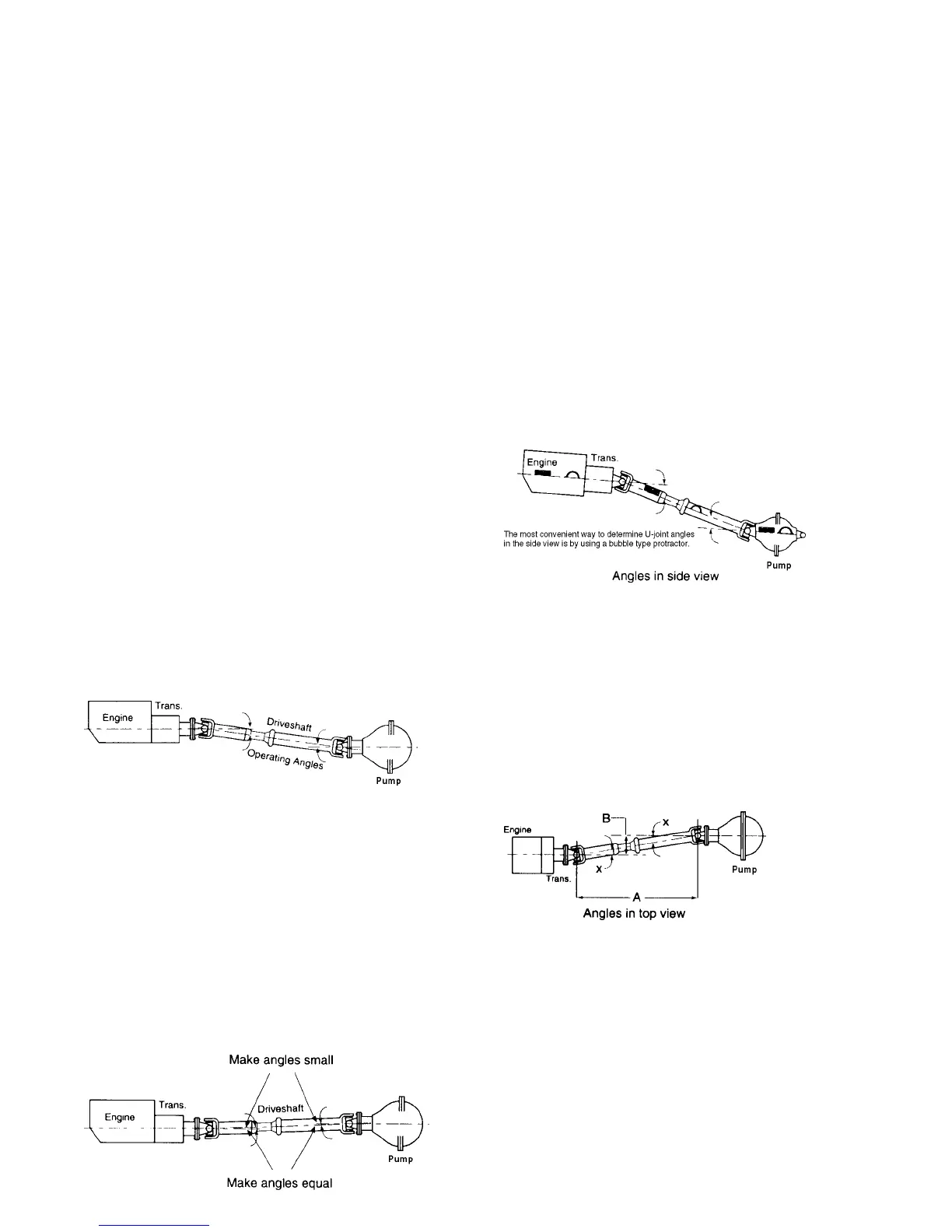
A u-joint operating angle is the angle that occurs at each
end of a driveshaft when the output shaft of the
transmission and the input shaft of the pump are not in
line. See figure.
The connecting driveshaft operates with an angle at
each u-joint. It is that angle that creates a vibration.
REDUCING AND CANCELING VIBRATION
A key point to remember about u-joint operating
angles: To reduce the amount of vibration, the
angles on each end of a driveshaft should always be
SMALL.
To cancel an angle vibration, the u-joint operating
angles need to be EQUAL within 1° at each end of a
shaft. See figure.
2-4-2. SINGLE PLANE AND COMPOUND
U-JOINT OPERATING ANGLES
There are two types of u-joint operating angles,
single plane and compound.
SINGLE PLANE
Single plane angles occur when the transmission and
pump components are in line when viewed from
either the top or side, but not both.
Determine the u-joint operating angle in an
application where the components are in line when
viewed from the top, but not in line when viewed
from the side, is as simple as measuring the slope of
the components in the side view, and adding or
subtracting those slopes to determine the angle. See
figure.
These angles should be SMALL and equal within 1°.
Determine the u-joint operating angles on a shaft
that is straight when viewed from the side and offset
when viewed from the top requires the use of a
special chart (See accompanying chart). In this type
of application, the centerlines of the connected
components must be parallel when viewed from the
top, as shown. These angles should also be SMALL
and equal within 1°. See figure.
Look at the angle chart and note that the smaller the
offset, the smaller the resultant angle.
To reduce the possibility of vibration, keep any
offset between connected points to a minimum.