OPERATION EN
DiBO 19
Operation
START WITH PETROL MOTOR HAND STARTED/ELECTRIC
STARTED
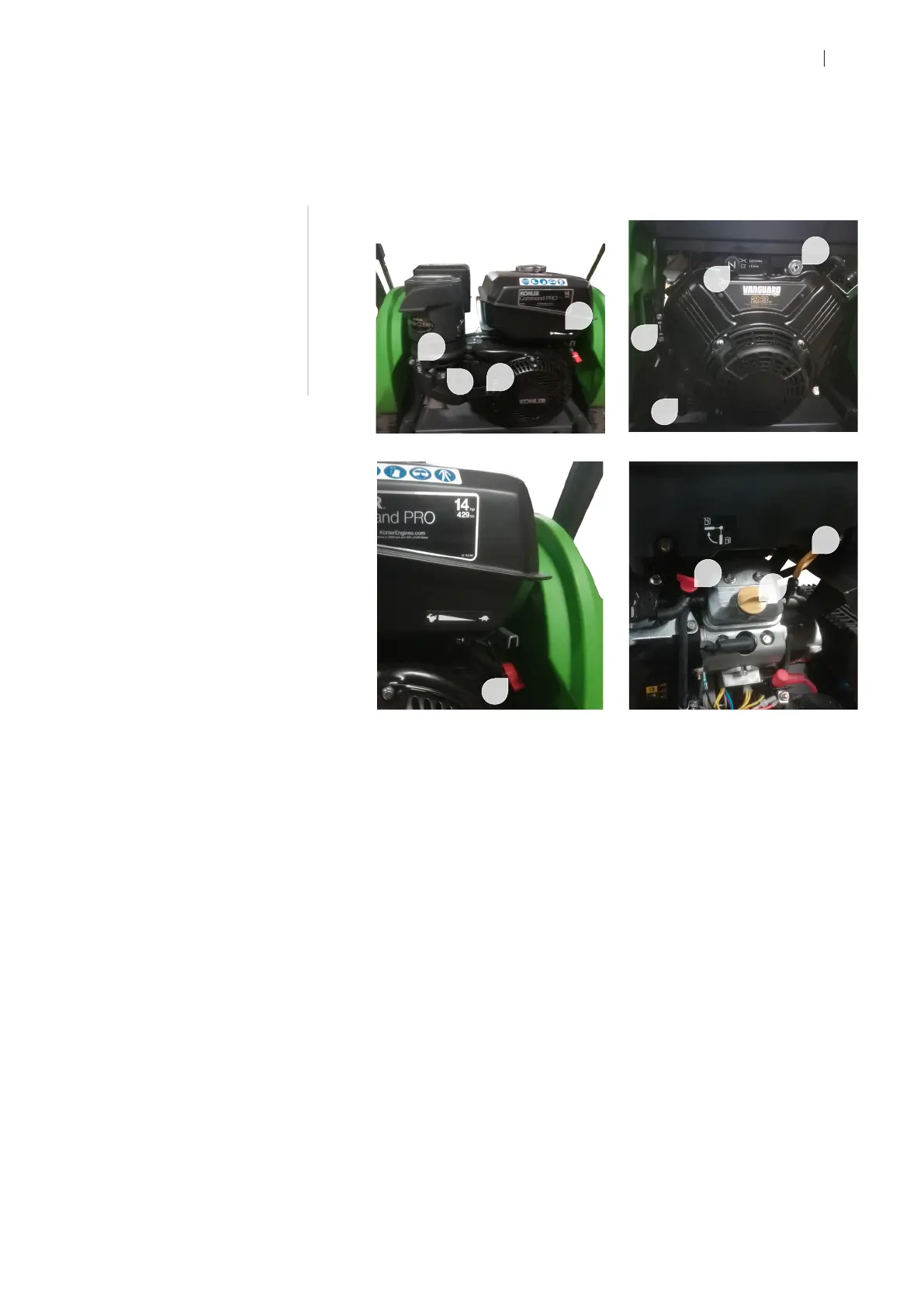
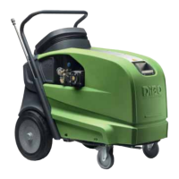
1 CHOKE CONTROL SYSTEM FIG 1 & 2
The choke lever is situated on the engine (both types) and has 2 positions:
• Not choking (working position, handle up to right stop or lever pushed in).
• Choking (handle up to the left or lever pulled out).
Warm start/ hot environment:
Do not choke. Choke handle stays to the right stop or pushed.
Cold start:
Choke according to the needs. Warm up the engine. Move the choke handle to
the right (or pushed in), so the engine gets warmer
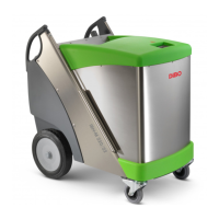
2 FUEL TAP FIG 1 & 4
The fuel tap has two positions:
• OFF or horizontal = no fuel ( tap to the left (PTL-M) or tap horizontally (PTL-L) )
@ engine out of use.
• ON or vertical = fuel (tap to the right (PTL-M or tap vertically (PTL-L) ) @ engine
in operation.
3 THROTTLE LEVER FIG 1 & 2
The throttle lever can only be applied in two positions (at PTL-L):
• Middle position = stationary number of revolutions (heating, cooling, short
break)
• 1 = full gas during cleaning activities
For info: At PTL-M happens the throttle control automatically via
the ETC controller. At not operating the spray gun, the motor will
be regulated to idle speed by the ETC. At operating the spray gun,
the motor will be regulated to maximum speed set by the ETC.
fuel tap
choke lever
throttle lever
starter cord
key contact
operating switch
oil fill cap
oil dipstick
2
3
4
1
3
5
4
2
6
1
7
8
FIG 1 - PTL-M
FIG 2 - PTL-L
FIG 3 - PTL-M
FIG 4 - PTL-L (right side)