EasyManua.ls Logo

Dickey-John IntelliAg User Manual

Dickey-John IntelliAg
175 pages
To Next Page IconTo Next Page
Page #1 background imageLoading...
Page #1 background image
IntelliAg PDC User 2 & 3
11001-1509A-201105
i
TABLE OF CONTENTS
Safety Notices ...................................................................................................... 1
System Overview ................................................................................................. 3
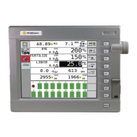
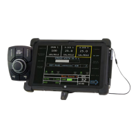
Virtual Terminal (VT).......................................................................................................... 3
Master Switch .................................................................................................................... 4
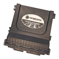
Working Set Master (WSMT) Module (Planter Drill Control).............................................. 4
Working Set Member (WSMB) Module (optional).............................................................. 5
Implement Lift Switch (optional)......................................................................................... 5
CAN Terminators ............................................................................................................... 5
System Requirements ......................................................................................... 7
Performance Features ....................................................................................................... 7
Compatibility ...................................................................................................................... 8
Installation ............................................................................................................ 9
Virtual Terminal.................................................................................................................. 9
Master Switch .................................................................................................................... 9
Working Set Master (WSMT) Module .............................................................................. 10
Working Set Member (WSMB) Module............................................................................ 12
Cab Harness Connections ............................................................................................... 15
Sensor Installation ........................................................................................................... 21
Seed Sensors.................................................................................................................................. 21
Hopper Level Sensors..................................................................................................................... 23
RPM/Fan Sensors........................................................................................................................... 23
Air Pressure Sensors ...................................................................................................................... 23
System Modes.....................................................................................................25
User Level Access ........................................................................................................... 25
Operate Mode .................................................................................................................. 25
Available Buttons in Operate Mode ................................................................................. 26
Setup/Configuration Mode ............................................................................................... 28
Available Buttons in Setup Mode ..................................................................................... 28
Planter Fill Disk ............................................................................................................................... 28
Row Monitor Setup.......................................................................................................................... 28
Control Setup .................................................................................................................................. 28
Speed Set ....................................................................................................................................... 29
Diagnostics...................................................................................................................................... 29
Alarm Log ........................................................................................................................................ 29
System Accumulators ..................................................................................................................... 29
Module Configuration ...................................................................................................................... 29
Screen Configuration ...................................................................................................................... 29
Planter Output Module (POM) Configuration (optional) .................................................................. 29
Configuration................................................................................................................................... 29
User Levels......................................................................................................... 31
User Level 1 Operator (Basic View)................................................................................. 31
Change Operator Level to OEM/Dealer Level ................................................................. 32

Table of Contents

Other manuals for Dickey-John IntelliAg

Questions and Answers:

Dickey-John IntelliAg Specifications

General IconGeneral
CategoryControl Systems
ManufacturerDICKEY-john
Product LineIntelliAg
ApplicationAgricultural Equipment Monitoring and Control
Featuresdata logging
ConnectivityUSB
CompatibilityCompatible with various agricultural machinery and software

Summary

Safety Notices

System Overview

Describes the IntelliAg Planter Drill Control system components and function.

Virtual Terminal (VT)

Provides user interface for IntelliAg system.

Master Switch

Starts and stops product application.

Working Set Master (WSMT) Module (Planter Drill Control)

Houses system's primary interface device.

Working Set Member (WSMB) Module (optional)

Auxiliary to Working Set Master for monitoring rows.

Implement Lift Switch (optional)

Detects implement position for automatic control.

CAN Terminators

Necessary for proper communication between system components.

System Requirements

Performance Features

Details system capabilities like user access levels and monitoring features.

Compatibility

Lists compatible sensors and equipment.

Installation

Virtual Terminal Installation

Instructions for installing the Virtual Terminal to the tractor cab.

Master Switch Installation

Steps for installing the Master Switch within reach of the operator.

Working Set Master (WSMT) Module Installation

Mounting instructions for the WSMT module on the implement.

Working Set Member (WSMB) Module Installation

Mounting instructions for the WSMB module on the implement.

Cab Harness Connections

Diagrams illustrating cab harness layout and connections.

Sensor Installation

Guidelines for connecting various sensors.

Seed Sensors

Details for connecting seed sensors.

Hopper Level Sensors

Details for connecting hopper level sensors.

RPM/Fan Sensors

Details for connecting RPM/Fan sensors.

Air Pressure Sensors

Details for connecting air pressure sensors.

System Modes

User Level Access

Describes the two user levels for system access.

Operate Mode

System is operational when Master Switch is ON.

Available Buttons in Operate Mode

Defines top-level buttons in Operate mode.

Setup/Configuration Mode

Mode for setting constants, requires password.

Available Buttons in Setup Mode

Defines buttons for system configuration and parameter setup.

User Levels

User Level 1 Operator (Basic View)

Restricted level for viewing, cannot change setup constants.

Change Operator Level to OEM/Dealer Level

Procedure to switch to full access level using a password.

System Configuration

Control Setup Overview

Overview of materials and configurations for control channels.

Material Setup Process

Recommended order for establishing materials and channels.

Material Setup - Planter Control

Setting parameters for planter control.

Material Setup - Gran Seed and Gran Fertilizer

Setting parameters for granular seed/fertilizer.

Material Setup - Liquid Flow

Setting parameters for liquid flow control.

Material Setup - Monitor Only

Setup for ground drive applications monitoring population.

Material Setup - RPM Control

Setting parameters for RPM control.

Control Channel Setup

Control Channel Types

Lists available control channel types: Planter, Granular, Liquid, RPM, Disabled.

Planter Control Setup

Setting a channel to control application rate of a row crop planter.

Granular Seed and Granular Fertilizer Setup

Defines parameters for granular seed/fertilizer.

Liquid Flow Setup

Defines parameters for liquid flow control.

RPM Control Setup

Defines parameters for RPM control.

Valve Calibration

Sets machine hydraulic system parameters for various controls.

Testing Procedures

Includes Continuous Test and 5 Rev Test for meter accuracy.

Ground Speed Calibration

Calibrates ground speed sensor for accurate readings.

Auxiliary Input/Function Assignment

Configures master switch input for system control.

Work Screen Configuration

Places data items on display by selecting location.

Summary Screen

Provides overview of setup constants for active control channels.

Data Items - Rates and Speed

Control Actual Channels

Displays actual application rates for channels 1-4.

Control Target Channels

Displays target set rates for channels 1-4.

Control Rate Channels

Displays calculated flow rates for channels 1-4.

Ground Speed

Displays the current ground speed of the tractor.

Data Items - Row Monitoring

Population Data

Displays row population, min/max, and average values.

Spacing Data

Displays row spacing, min/max, and average values.

Seed/Distance Data

Displays seeds per foot/meter for rows and averages.

Singulation Data

Displays singulation average and row scan data.

Data Items - Area Accumulation

Total Area

Displays area covered by the implement.

Field Areas

Displays area covered by Field 1 and Field 2.

Channel Areas

Displays area covered by Control Channels 1-4.

Data Items - System Status and Sensors

Material Accumulation

Displays accumulated material for channels 1-4.

Product Level

Indicates product remaining in hopper/tank.

Hopper Level Status

Indicates empty or nonempty hopper status.

RPM Scan

Displays actual RPM for shaft/fan sensors.

Pressure Scan

Displays actual pressure measured by sensors.

Boom Status

Indicates status of each boom section.

Guidance Status

Displays guidance information like AutoPilot status.

System Active Time

Records time the system has been active.

Seed Count Accum Row

Displays seed count for each row.

Distance Accumulator

Displays distance covered in feet (meters).

System Operation

System Start and Stop

Procedures for starting and stopping the system operation.

Operate Screen Symbols

Explains symbols used in Operate mode.

System Status and Diagnostics

Accesses screens for system status, diagnostics, and alarms.

Precharge Feature

Dispenses material at a set rate for a duration.

Flush Enable

Dispenses material at a higher rate when below shutoff speed.

Task Controller

Implement Offset

Determining implement offset for calculations.

Calculating Implement Offset

Distance from channel center to hitch/GPS point.

Channel Linking

Linking control channels for simultaneous rate changes and on/off control.

Material Application Rates

Resets system to IntelliAg rates or selects current rates.

Import/Export Data

Transferring configurations between machines via SD card.

Troubleshooting & Alarms

Alarm Indication and Acknowledgment

How alarms are indicated and acknowledged.

Alarm Log and Details

Lists specific alarms, their occurrences, and details.

Alarm Reset

Clears the Alarm Log.

Alarm Causes and Corrections

Lists alarm numbers, probable causes, and corrective actions.

Appendix

System Configuration Worksheet - Module Setup

Worksheet for configuring modules.

System Configuration Worksheet - Channel Configuration

Worksheet for configuring control channels.

System Configuration Worksheet - Work Screen

Worksheet for configuring work screens.

Work Screen Worksheet - Material Setup (INC/DEC)

Worksheet for material setup using Inc/Dec.

Work Screen Worksheet - Material Setup (PRESET)

Worksheet for material setup using Preset.

DICKEY-john® WARRANTY

Warranty Terms and Limitations

Details warranty coverage, exclusions, and purchaser acceptance.

Related product manuals