EasyManua.ls Logo

Dickey-John Control Point - User Manual

Dickey-John Control Point
109 pages
Print Icon
To Next Page IconTo Next Page
Loading...
CONTROL POINT
®
CONTROL SYSTEM
Operator’s Manual
SINCE 1966
®

Table of Contents

Questions and Answers

  • S
    Stephen WhiteAug 14, 2025
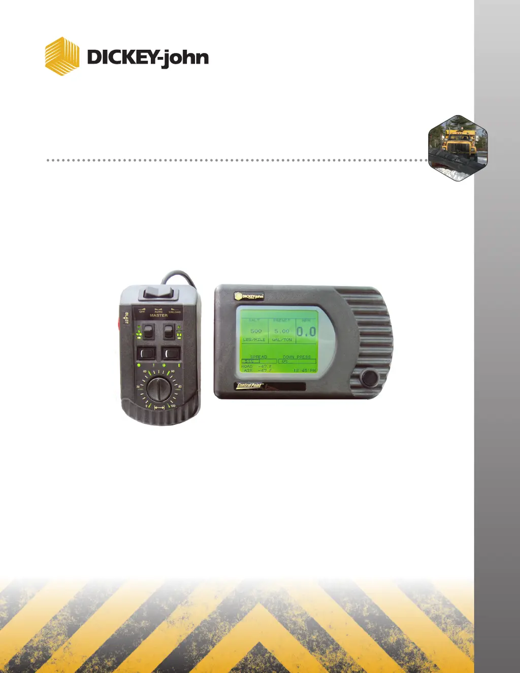
    Why Dickey-John Control Point console does not power on?
    • N
      nboyleAug 14, 2025
      If your Dickey-John Control System console won't power on, first, check the fuse in the positive battery lead and replace it if it's blown, using the same size blade-type fuse. Next, inspect battery connections for corrosion and ensure correct battery polarity. Then, check the red ignition wire and the power cable from the console to the battery for damage, replacing or repairing as needed. If these steps don't solve the problem, the console itself may be faulty.
  • J
    jason07Aug 17, 2025
    What to do if AUTO is inoperative, but UNLOAD operates on Dickey-John Control Systems?
    • D
      dthorntonAug 17, 2025
      If the AUTO function isn't working but UNLOAD operates on your Dickey-John Control Systems, the ground sensor might be the issue. First, check the ground speed reading (MPH) on the console. If it reads 0 while the truck is moving, inspect the wires and connections between the Dickey-John ground speed sensor and the console, and between the sensor and the transmission speed sensor. Next, check the ground speed calibration number (F7) in the console, ensuring it's between 35000 and 60000. If problems persist, replace the ground speed sensor, and if needed, the MASTER switch module and then the console.
  • P
    patrickkaneAug 21, 2025
    How to fix application rate error on Dickey-John Control Point Control Systems?
    • A
      Andrea MillerAug 21, 2025
      If you're encountering an application rate error with your Dickey-John Control Systems, first, reduce the truck's ground speed to allow the system to catch up. You can also shift to a lower gear to increase engine RPM and hydraulic pump rotation. Check the hydraulic disconnects and filter. Ensure the correct spreader constant is programmed into the console by checking the original setting or running a Granular Calibration (F6). Also, verify the PWM SAT setting in the Granular Configuration screen (F3) against the original or run System Response on the Granular channel (F11). Finally, check for sufficient hydraulic oil flow at normal engine RPM, and inspect the spreader valve, electrical connections, coil resistance, and voltage from the control console.
  • K
    kevinevansAug 25, 2025
    What to do if MANUAL MODE flashes on Dickey-John Control Point Control Systems display?
    • R
      rvincentAug 25, 2025
      If 'MANUAL MODE' is flashing on your Dickey-John Control Systems display, here's what to check: * If material isn't spreading (conveyor or auger stopped): * Ensure the PTO is engaged. * Check for lodged obstacles in the conveyor or auger. * Check for a hydraulic system failure (pump, valve, hydraulic motor). * If material is spreading (conveyor or auger turning): * Check for a disconnected or slipping conveyor sensor coupling. * Unplug the connector nearest the conveyor sensor and check for +12V between the RED and BLK wires and +8V between the GRN and BLK wires. Absence of either voltage indicates a broken or shorted wire or a corroded pin. If voltages are present, replace the conveyor sensor.
  • C
    Caleb Alexander MDAug 27, 2025
    Why does the displayed APR fluctuate on Dickey-John Control Point?
    • D
      Dr. Emily Holmes MDAug 27, 2025
      If the displayed APR fluctuates on your Dickey-John Control Systems, it could be due to the System Response (SYS RSPNS) constant being too large. Also, check the APR sensor for loose coupling or slipping on the shaft.
  • D
    Dr. Amanda WardAug 31, 2025
    How to correct spinner rotational speed on Dickey-John Control Point Control Systems?
    • M
      Maria AdamsAug 31, 2025
      If the spinner rotational speed is incorrect on your Dickey-John Control Systems, start by checking the PWM OFFSET and PWM settings in SPINNER mode (F8). Also, check for variations in granular material density dropping onto the spinners. For proportional valves, increased electrical coil resistance due to heat can cause speed changes. Finally, check for drag due to snow and ice buildup.
  • S
    Stephanie BrownSep 2, 2025
    What to do if convey/auger does not reach maximum speed on Dickey-John Control Point?
    • H
      Hannah MartinSep 2, 2025
      If the conveyor/auger on your Dickey-John Control Systems isn't reaching maximum speed, you can try the following: repair the hydraulic system, eliminate any binding, adjust to the proper pressure or replace the valve, clear any obstructions, or shift to a lower gear and/or axle.
  • R
    rcoxSep 6, 2025
    Why displayed APR responds slowly on Dickey-John Control Point Control Systems?
    • R
      Ryan BensonSep 6, 2025
      If the displayed APR responds slowly on your Dickey-John Control Systems, the System Response (SYS RSPNS) constant may be too small.
  • J
    Jason ShermanSep 9, 2025
    What to do if conveyor/auger does not run in either AUTO or UNLOAD on Dickey-John Control Systems?
    • M
      Manuel PhamSep 9, 2025
      If the conveyor/auger on your Dickey-John Control Systems isn't running in either AUTO or UNLOAD mode, try the following: engage the pump, open the valve, reconnect any disconnections, clear any jams, adjust or replace parts as needed, and repair any leaks and refill the oil.

Summary

Safety Notices

Introduction

Liquid Channel Configuration

Manages the application rate of liquid materials like pre-wetting or de-icing agents.

Spinner Channel Configuration

Controls spinner plate speed for even material coverage across the spread width.

Product Application Mechanisms

Details the components and features of the system for applying different types of materials.

Granular Channel Configuration

Configures the system for dispensing granular materials, controlling dump amounts and conveyor speed.

System Installation

Hardware Kits

Lists standard and optional hardware kits required for mounting system components.

Start-up and Familiarization

Start-up Preparation

Ensures system is installed, programmed, and calibrated before initial use.

Start-up Procedure

Step-by-step guide for powering on the system and basic operation checks.

Keyboard Programming

Logging Configuration Data

Procedure for recording system parameters for data backup and recovery purposes.

Pre-programming

Information on factory pre-programmed settings and custom configuration options.

Using the Keyboard and Screens

Guide on navigating menus and entering data using the system keyboard and display.

System Calibration

Recording Calibration Data

Instructions for documenting calibration constants on record sheets for future reference.

Repeating Calibration Runs

Recommendations for ensuring accuracy by performing calibration tests multiple times.

Maintaining Calibration Accuracy

Guidelines for periodic recalibration to ensure ongoing system accuracy.

Appendix A Converting Constants

Fine Tuning Application

Methods for adjusting spreader constants to fine-tune material application accuracy.

Calculating Spreader Constants

Formulas and steps to calculate spreader constants for various materials and settings.

Warranty

Dickey-John Control Point Specifications

General IconGeneral
ManufacturerDickey-John
CategoryControl Systems
DisplayLCD
Power Supply12 VDC
Humidity0% to 95% non-condensing
ApplicationAgricultural equipment control

Related product manuals