OPERATOR’S MANUAL
Control Point
®
11001-1489-201702 Rev B
SYSTEM INSTALLATION / 11
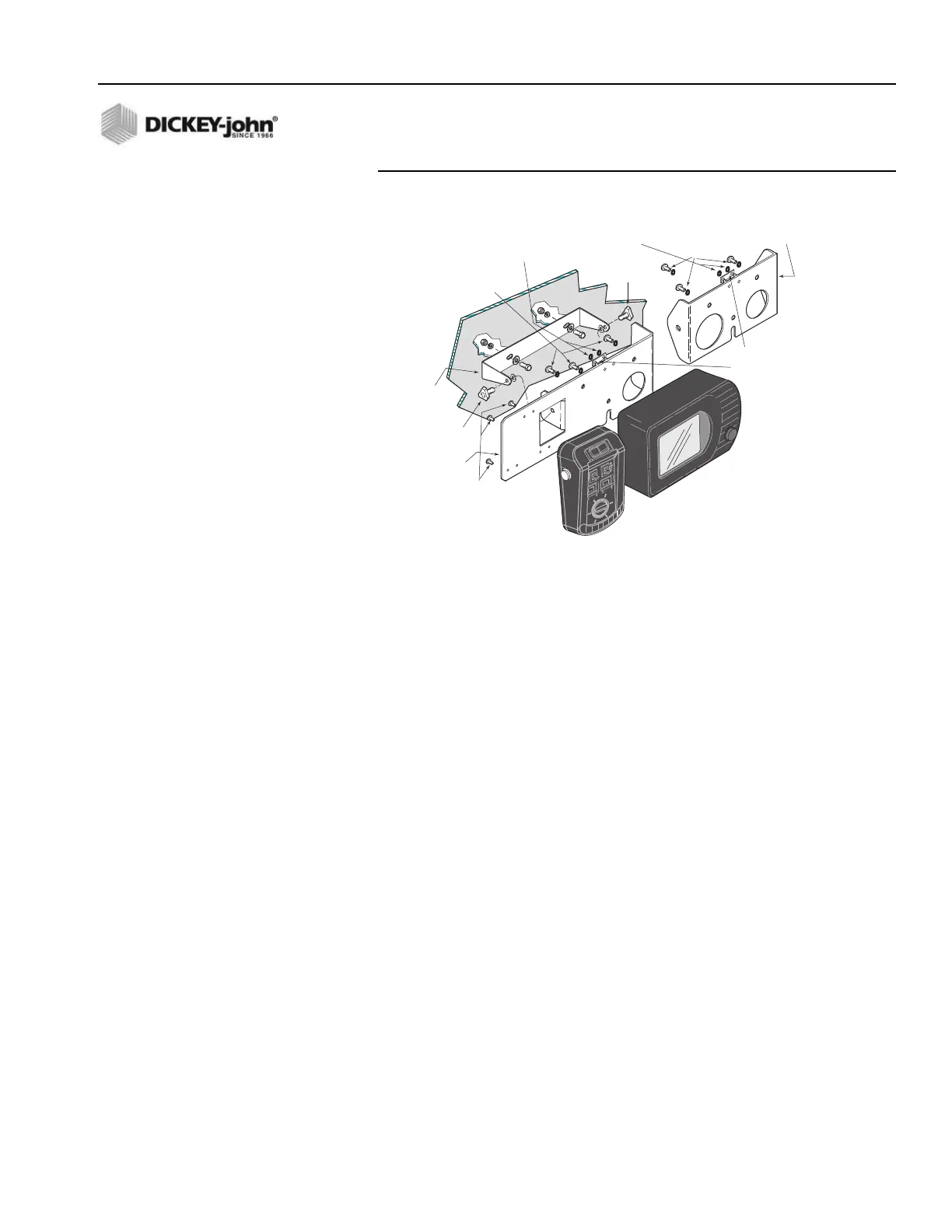
Figure 3
Console Mounting
SWITCH MODULE TO CONSOLE CONNECTION
1. Plug the circular connector of the Switch Module cable into the rear of
the Console, rotating the connector collar fully-clockwise to lock it.
2. Place the keyboard mating connector (with its pins pointing upward)
between the two studs on the rear of the mounting plate. Capture this
connector with the retaining clip and two self-locking nuts. The 9-pin
RS-232 connector can be secured to the Switch Module cable with a
cable tie, if desired. Figure 1 shows how the Switch Module cable
connects to the Console and keyboard.
CONSOLE MOUNTING
1. Secure the Console and mounting plate (and Switch Module if the
combination mounting plate is being used) to the U-bracket using the
two knob screws. The rubber washers fit between the U-bracket and
the mounting plate tabs.
2. Pivot the Console for the best viewing angle and tighten the two knob
screws.
HARNESS CONNECTION
1. Verify all required “exterior system cables” are installed on the
spreader vehicle according to their separate, individual instructions.
These are defined as the sensor, actuator, ground speed, boom sense,
and hopper level cables.
2. Use dust caps provided on all unused connectors, both internal and
external. This includes keyboard and RS-232 connectors.
U-Bracket
(46649-0590)
Combination
Mounting Plate
(46649-0580)
Optional Console Only
Mounting Plate
(46649-0370)
#6 Self-Locking
Hex Nuts
#6 Self-Locking
Hex Nuts
#6 x 1/2 inch
Plastite Screws
Knob Screw
(20072-0022)
Knob
Screw
(20072-0022)
1/4-20 x 3/4 Inch
Hex Bolts &
Lockwashers
1/4-20 x 3/4 inch
Hex Bolts &
Lockwashers
Retaining Clip
(holds Switch Mod
keybd connector)
(46649-0350)
Note: Mounting hardware for securing
mounting bracket to dash/mounting
panel are not supplied with kit.