OPERATOR’S MANUAL
Control Point
®
11001-1489-201702 Rev B
4 / INTRODUCTION
LIQUID CHANNEL CONFIGURATION
The liquid channel controls the application rate of pre-wetting or de-icing
materials. When pre-wetting, the Control Point® console monitors a
flowmeter-style feedback sensor. Flowmeter feedback can be used when
de-icing. Using feedback data, the pumping mechanism output adjusts the
target application rate by either regulating pump speed or flow blocking.
De-icing systems use up to five boom inputs for applying material to more
than one lane at a time.
SPINNER CHANNEL CONFIGURATION
The spinner channel controls the spinner plate(s) speed with either a
closed-loop (precision) or an open-loop configuration. In the closed-loop
configuration, a tachometer style feedback sensor, mounted on the spinner
assembly, monitors spinner activity. Using the feedback data, the spinner
mechanism speed adjusts for the target setting by controlling the hydraulic
valve position. In open loop systems, the hydraulic valve position is relative
to the width adjust knob setting on the Control Point
®
Switch Module.
The user must determine the spread-width accuracy needed. Technical
assistance is available through DICKEY-john Technical Support at
PH#1-800-637-2952.
PRODUCT APPLICATION MECHANISMS
The granular and spinner channels use, in addition to feedback (shaft
rotation) sensors, proportional valves to control the product application and
spinner speed. The liquid channel uses, in addition to feedback sensors
(flowmeter), a liquid pump to control product application. The liquid pump
output is controlled by either a 12 volt DC motor, servo valve actuator, or
proportional valve.
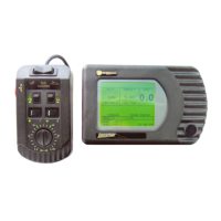
Features:
1. Surface-mount console kit for ease of installation.
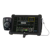
2. Flexible Switch Module design allows mounting anywhere in the cab
for optimal operator use.
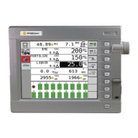
3. Large 160X128 dot-matrix LCD display with backlighting for nighttime
viewing.
4. Single Console button for system power on/off and screen selection.
5. RS-232 port for PC uploading and downloading of data.
6. Detachable keyboard for easy supervisor programming and calibration
using multilevel, menu-driven screens.
7. Custom programming available to minimize setup time.
8. Compatibility with a variety of sensors, servo valve actuators, and
proportional valves available from DICKEY-john or other
manufacturers.
9. Audible and visual alarms for system and operator errors.