OPERATOR’S MANUAL
Control Point
®
11001-1489-201702 Rev B
SYSTEM INSTALLATION / 13
CHECKING OPERATION
1. After completing the installation, turn on the ignition switch. The
Console screen should power on displaying the DICKEY-john name,
logo screen, software version, and then the OPERATE screen (refer to
Figure 9).
2. Refer to the Startup and Familiarization section for additional testing.
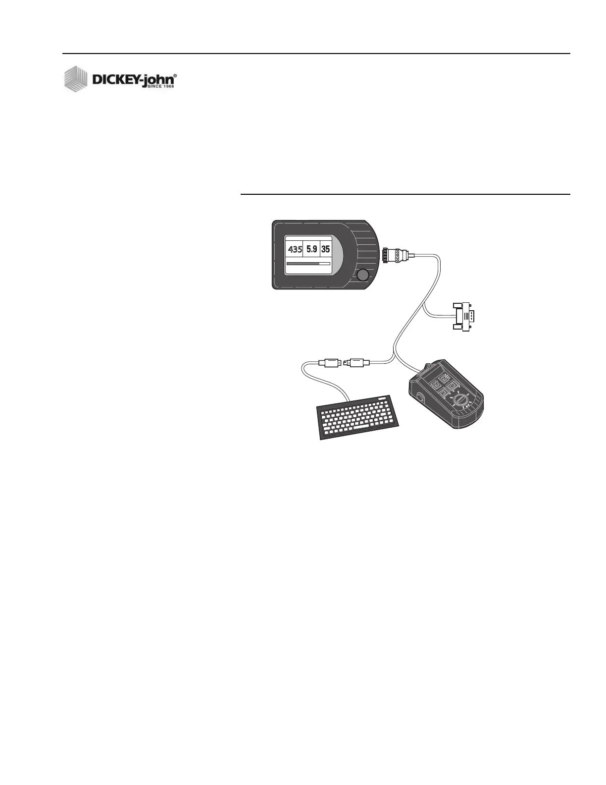
Figure 4
Switch Module Cabling
435
SALT
LBS/MILE
LIQUID
GAL/TON
MPH
0% 100%
SPREAD WIDTH
8 MAR
12:25:PM
1
2
3
4
5
6
7
8
9
0
-
=
Q
W
E
R
T
Y
U
I
O
P
[
]
\
A
S
D
F
G
H
J
K
L
;
'
Back
Space
Z
X
C
V
B
N
M
,
.
/
RS232
Connector
for
Computer
Display Console
Keyboard
Connectors
Switch
Module
Keyboard
Connects to
Rear side of Console
OFF AUTO UNLOAD
MASTER
0
0
40
60
80
100
BLAST