OPERATOR’S MANUAL
Control Point
®
11001-1489-201702 Rev B
INTRODUCTION / 5
SYSTEM COMPONENTS
A DICKEY-john Control Point
®
system consists of six basic components:
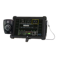
1. Console
2. Switch module
3. Ground speed sensor
4. Feedback devices to monitor material application
5. Valve control devices to regulate material application
6. Harnesses to interconnect all system devices
NOTE: The detachable keyboard
(optional) and PC (not
provided) are programming
aids and are not part of a basic
Control Point
®
system.
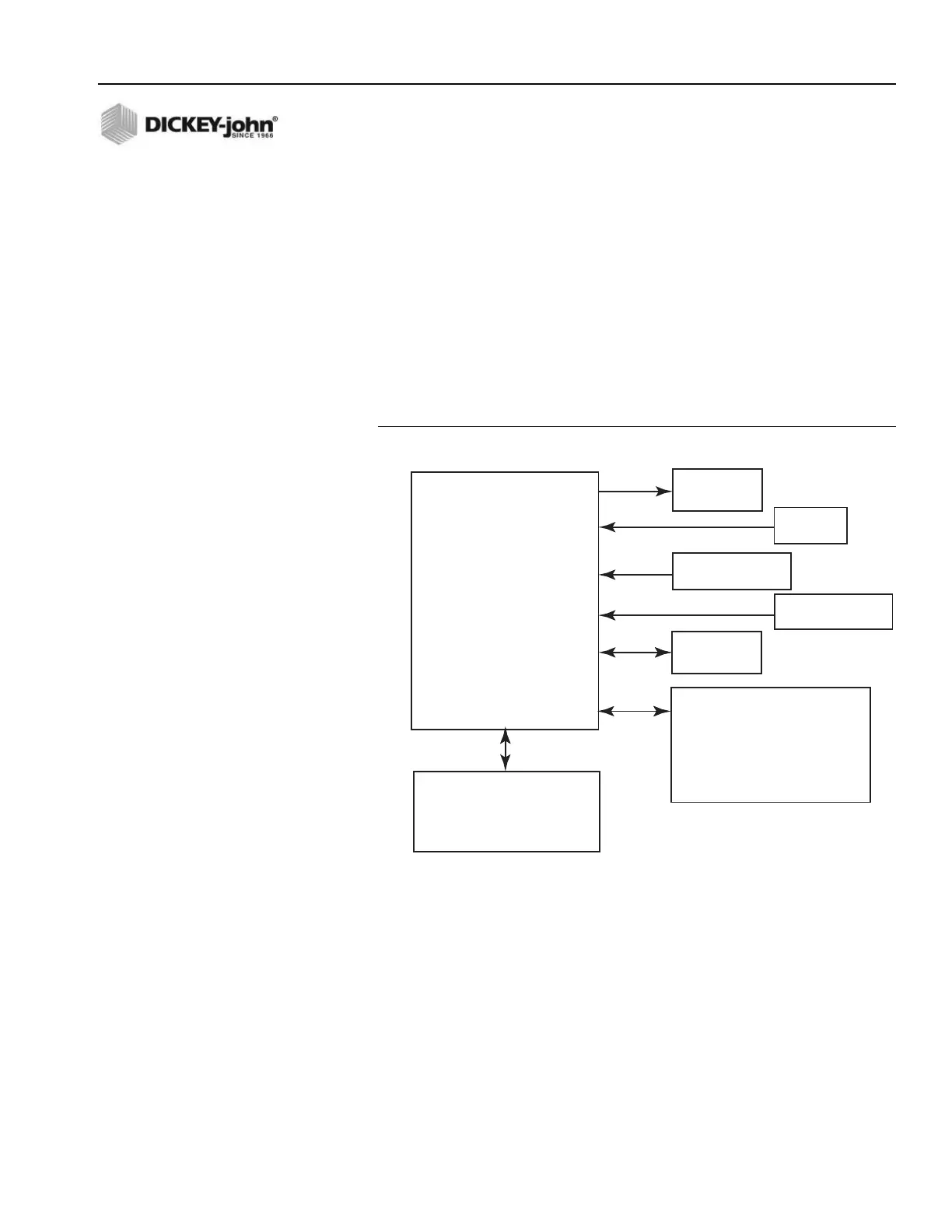
Figure 2 shows components in a block diagram. The Console and Switch
Module are to be mounted inside the truck cab either side-by-side or the
Switch Module positioned elsewhere for operator convenience.
Figure 2
System Block Diagram
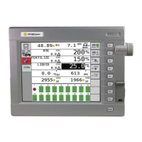
CONSOLE
The Console displays information on a dot-matrix LCD and uses a single
push-button switch to control system power and to view several operator
screens. Using an external keyboard for programming and placing operator
controls on the Switch Module simplifies the Console.
CONSOLE
• Store User Entered and
Accumulated Data
• Transfer User Entered and
Accumulated Data
• Display APRs (2)
• Display Spread Width
• Display Ground Speed
• Display Time & Date
• Display Current Totals
• Display Season Totals
• Control 3 Channels
KEYBOARD
• Alphanumeric Data Entry
• Program, Calibrate
• Service Access
SWITCH MODULE
• Master OFF/AUTO/UNLOAD
• Channel ON/OFF
• Channel APR INC/DEC
• BLAST Switch
• Spread WIDTH ADJUST Knob
3 Channel
Actuators
Gnd Spd
Sensor
3-Pulsed Feedback
Sensors
3-Analog Feedback
Sensors
RS232 Port