Digi Connect and ConnectPort TS Family web interface Configuration through the web interface
Digi Connect Family and ConnectPort TS Family
68
Character
Key
Sequence
backspace \b
formfeed \f
tab
\t
line feed
\n
return \r
backslash
\\
hexadecimal
values
\xhh
Display current serial port settings
To display the current serial port settings for a Digi device, type display techsupport from the
command line interface.
GPIO pins
This section applies only to embedded products. All Digi Connect Family embedded devices have
several GeneralPurpose IO (GPIO) pins. In normal operation, GPIO pins are used for the serial signals
CTS, DCD, DSR, DTR, and RTS. On Digi Connect EM and Wi-EM, both sets of RXD/TXD signals are also
configured. You can use these GPIO pins for either standard serial communication signaling or a user-
defined purpose, such as when a significant event occurs in the device. In the latter case, you can
configure the Digi device so that when an event occurs, an alarm is sent as an email message to an
administrator or technician, or as an SNMP trap. The number of GPIO pins varies by device. Digi
Connect ME and Wi-ME devices have five GPIO pins, while Digi Connect EM and Wi-EM devices have
nine GPIO pins. You can view the configuration and current state of GPIO pins through the web
interface or by issuing commands from the command line.
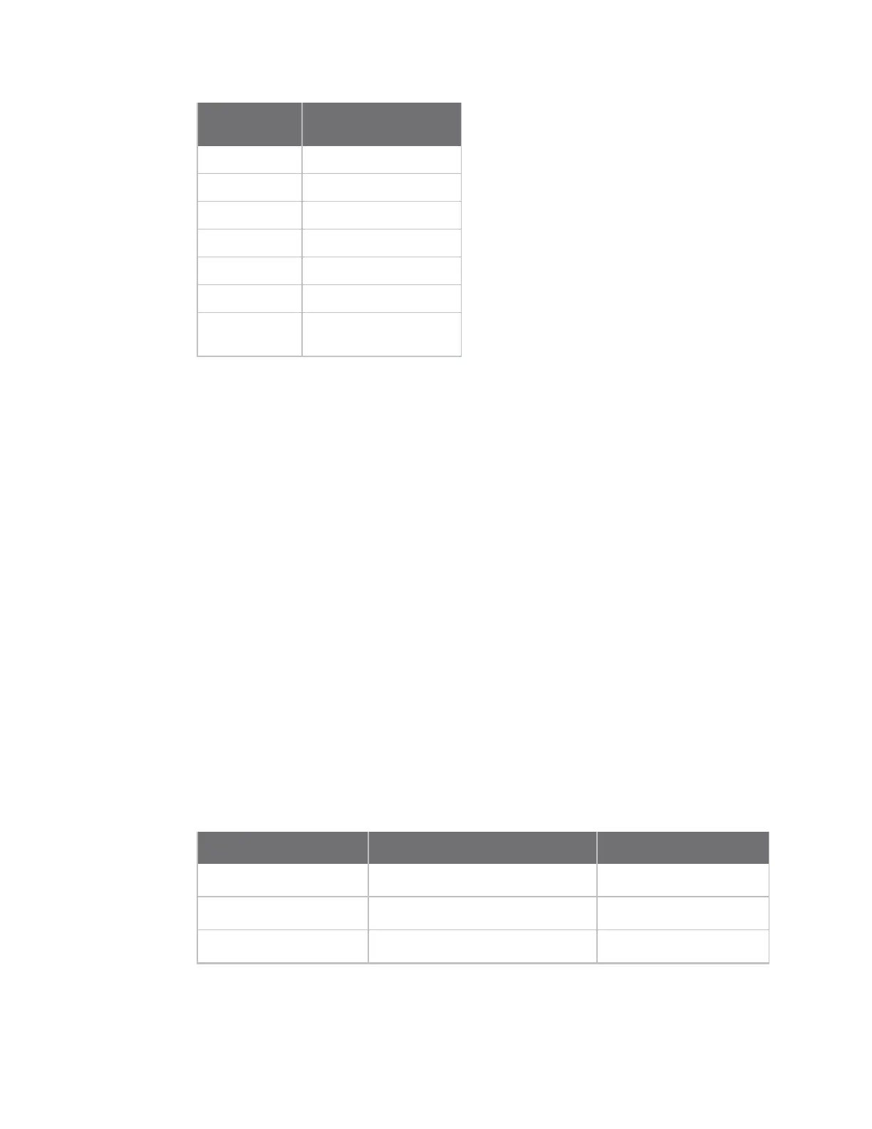
GPIO pin settings
The GPIO Configuration page configures GPIO pin settings. You can configure GPIO pins configured for
one of three modes: serial, input, and output.
n Serial: Use the GPIO pin for standard serial communication signaling. Each pin maps to a
different serial signal: DCD, CTS, DSR, and so on. The following table lists the default serial
settings for the GPIO pins on a Digi device. Depending on the device, there are five or nine pins.
Pin Number Default Serial Signal Signal Direction
GPIO 1 DCD Input
GPIO 2 CTS Input
GPIO 3 DSR Input