Pin signals Pin signals for the XBee 3 surface-mount module
Digi XBee® 3 RF Module Hardware Reference Manual
24
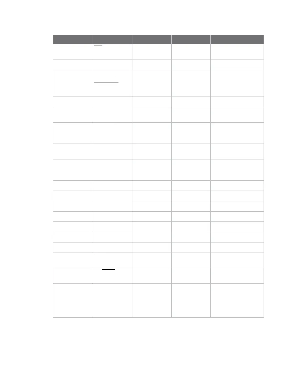
Pin# Name Direction Default state Description
10 DTR/SLEEP_RQ
/DIO8
Both Input Pin sleep control
Line/GPIO.
11 GND - - Ground.
12 SPI_ATTN/
BOOTMODE
/DIO19
Output Output
Serial peripheral
interface attention .
Do not tie low on reset.
13 GND - - Ground.
14 SPI_CLK /DIO18 Input Input Serial peripheral
interface clock/GPIO.
15 SPI_SSEL/DIO17 Input Input Serial peripheral
interface not
select/GPIO.
16 SPI_MOSI/DIO16 Input Input Serial peripheral
interface data in/GPIO.
17 SPI_MISO/DIO15 Output Output Serial peripheral
interface data
out/GPIO.
18 [reserved] - Disabled Do not connect.
19 [reserved] - Disabled
Do not connect.
20 [reserved] - Disabled
Do not connect.
21 [reserved] - Disabled
Do not connect.
22 GND - - Ground.
23 [reserved] - Disabled Do not connect.
24 DIO4 Both Disabled GPIO.
25 CTS/DIO7 Both Output Clear to send flow
control/GPIO.
26 ON/SLEEP/DIO9 Both Output Device status
indicator/GPIO
27 [reserved] - Disabled
Do not connect or
connect to Ground.

 Loading...


