Pin signals Pin signals for the XBee 3 surface-mount module
Digi XBee® 3 RF Module Hardware Reference Manual
25
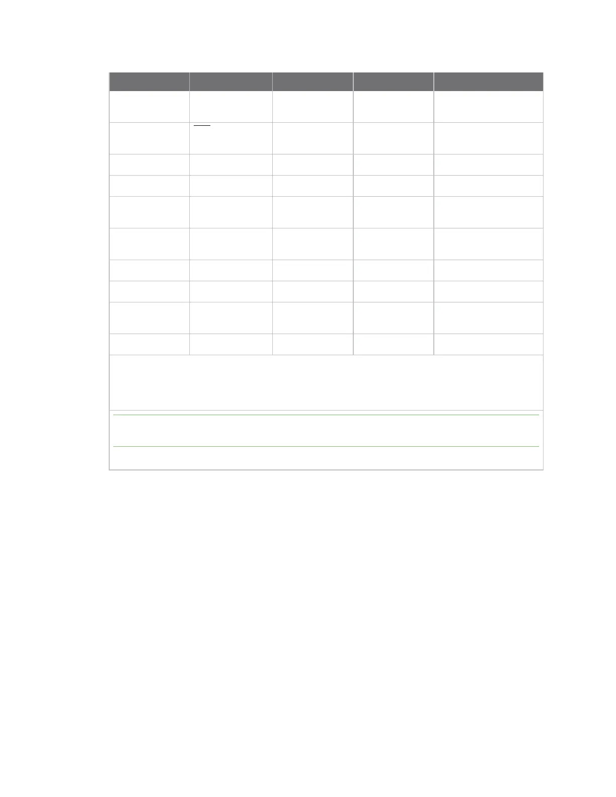
Pin# Name Direction Default state Description
28 ASSOCIATE/DIO5 Both Output Associate
Indicator/GPIO.
29 RTS/DIO6 Both Input Request to send flow
control /GPIO.
30 AD3/DIO3 Both Disabled Analog input/GPIO.
31 AD2/DIO2 Both Disabled
Analog input/GPIO
32 AD1/DIO1/I2C
SCL
Both Disabled
Analog input/GPIO/I2C
SCL.
33 AD0 /DIO0 Both Input Analog input / GPIO /
Commissioning button.
34 [reserved] - Disabled Do not connect.
35 GND - - Ground.
36 RF Both - RF I/O for RF pad
variant.
37 [reserved] - Disabled Do not connect.
Signal direction is specified with respect to the device.
This is a complete list of functionalities. See the applicable software manual for available
functionalities.
Note There are a possible three RF test points located on the bottom of the device. Do not connect
these test points. For more information, see Recommended footprint.
See Design notes for details on pin connections.

 Loading...


