192 I/O Guide6
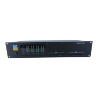
Loop Master LED
The LOOP MASTER LED indicates which
Pro Tools|HD audio interface is the master
Pro Tools peripheral. The Loop Master LED will
be continuously lit on the current Loop Master
peripheral only, and unlit on all other peripher-
als. (Only one Pro Tools|HD I/O can be Loop
Master at a time.) The Loop Master LED will al-
ways be lit with a single interface.
Loop Master defaults to the first Pro Tools|HD
peripheral connected to the primary, or “core”
Pro Tools|HD card. On Pro Tools|HD (for PCIe)
this is the Accel Core card. On Pro Tools|HD (for
PCI) this is the HD Core card.
Sync Mode LEDs
The SYNC MODE LEDs indicate the current
Clock Source as set in Pro Tools.
INT (Internal) Indicates the 192 I/O sample clock
is generated by its internal crystal oscillator, as
determined by the session Sample Rate.
DIG (Digital) Indicates that an external AES/EBU,
TDIF, Optical (ADAT), or S/PDIF device is pro-
viding system clock. If no valid clock source is
detected, 192 I/O will switch to INT, the DIG
LED will flash, and an error message will appear
on-screen in Pro Tools.
If at least two channels are not assigned from
the selected digital port in the Main page of the
Hardware Setup dialog, or if no valid clock
source is detected at this port, 192 I/O will
switch to INT and the DIG LED will flash.
LOOP (Loop Master) Indicates that the 192 I/O is
slaving to another Pro Tools|HD I/O through
Loop Sync. You do not set LOOP mode any-
where in the software. This is done automati-
cally when you choose another peripheral as
LOOP MASTER.
EXT (External) Indicates that the 192 I/O is us-
ing the EXT CLOCK IN port for system synchro-
nization.
External Clock input and output do not have to
be at the Word clock rate. EXT CLOCK IN syn-
chronization will typically be 1x the current ses-
sion sample rate. However, for sample rates
higher than 48 kHz, the 192 I/O will generate a
choice of 1x or a base rate of 44.1 kHz or 48 kHz,
depending upon the higher rate, as follows:
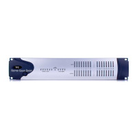
Meters
These four-segment LEDs indicate signal level
for each of the sixteen channels. The top row of
meters indicates input levels, and the bottom
row shows output levels. These meters are cali-
brated at –42 dB, –18 dB, –6 dB, and 0 dB, respec-
tively.
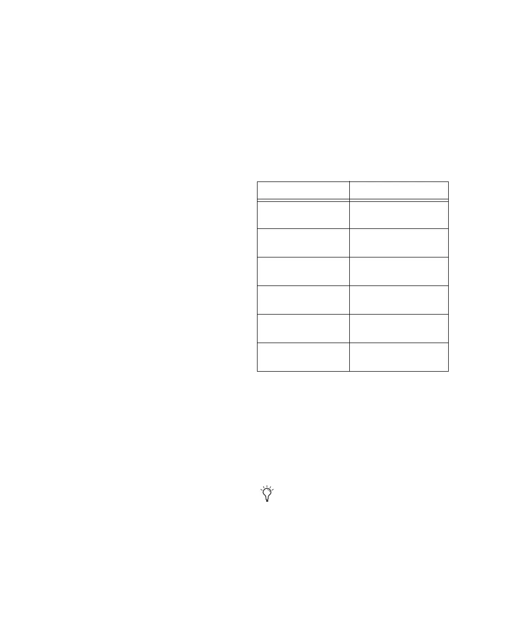
Session Sample Rate Word Clock Support
44.1 kHz 44.1 kHz
(or 256x out)
48 kHz 48 kHz
(or 256x out)
88.2 kHz 88.2 kHz
44.1 kHz
96 kHz 96 kHz
48 kHz
176.4 kHz 176.4 kHz
44.1 kHz
192 kHz 192 kHz
48 kHz
Note that 0 dB is not to be confused with
clipping; use the on-screen meters in
Pro Tools to determine whether a signal is
clipping. See the
Pro Tools Reference Guide.