Chapter 2: Hardware Overview and Stand-Alone Operation 5
chapter 2
Hardware Overview and Stand-Alone
Operation
This chapter describes the PRE front and back panels, and includes instructions for using its switches,
indicators, and connectors for Stand-alone mode operation. To use PRE in Remote mode (remote con-
trol of PRE by Pro Tools or a dedicated control surface), see Chapter 3, “Remote Operation.”
PRE Front Panel
PRE has the following front panel switches, indicators, and connectors:
Power Switch and LED Ring
This switch turns PRE on and off. When lit
(green), the LED ring around the power switch
indicates that the unit is switched on.
By default, PRE powers up in Stand-alone mode.
In this mode, controls can be adjusted from the
front panel or remotely. The Remote “Lock-
Out” LED is unlit (signifying Remote Lock-Out
mode is inactive).
At power up, PRE units default to the last set-
tings they had at power down, with the excep-
tion of Remote Lock-Out mode.
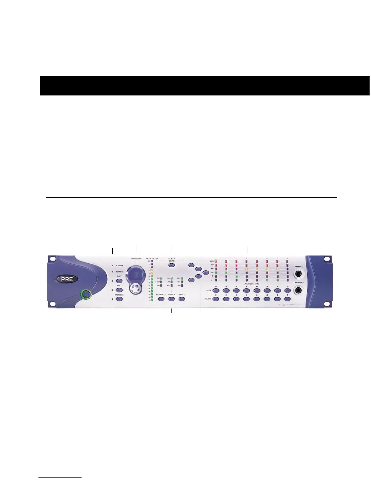
PRE front panel
Activity and Remote LEDs
Channel Select and Mute
switches and LEDs
Shift, Oscillator, and
MIDI Chan switches
Line/Inst 1 and 2
Gain/Param
Power switch,
and LED ring
Peak Meter
Clear Clips
Peak Hold, Source,
and Input Impedance
Signal Present/Clip, 48V, Insert, Pad,
Phase, and High-Pass Filter indicators
48V, Insert, Pad, Phase,
and High-Pass Filter