Nexys 3™ FPGA Board Reference Manual
Copyright Digilent, Inc. All rights reserved.
Other product and company names mentioned may be trademarks of their respective owners.
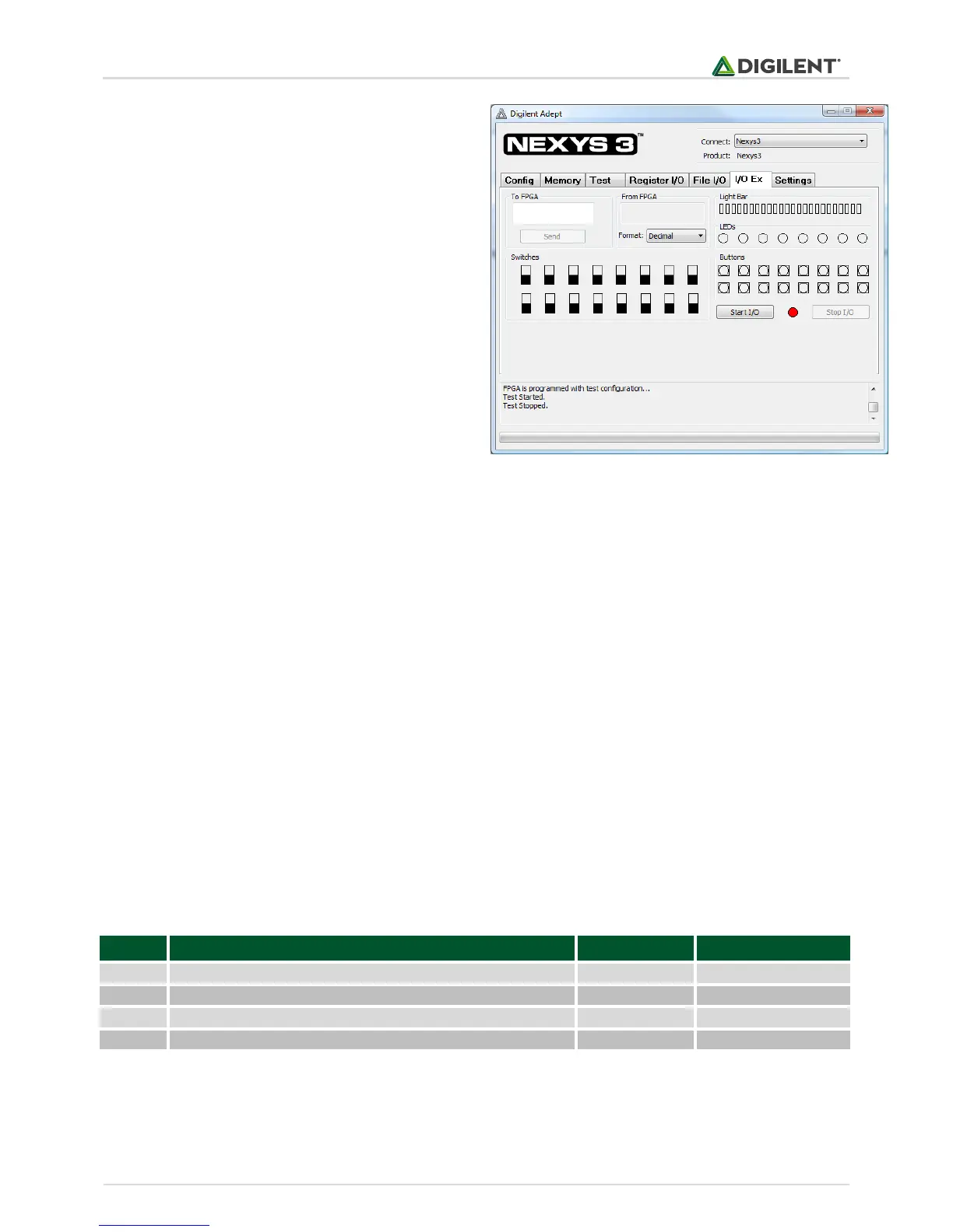
The IP block, available in the Adept I/O Expansion
reference design (AdeptIOExpansion.zip) on the Adept
page of the Digilent website, provides a simple interface
with well-defined signals. This IP block can easily be
included in, and accessed from, user-defined circuits.
For more information, see the Adept documentation
available at the Digilent website.
2 Power Supplies
The Nexys 3 board can receive power from the Adept USB port or from an external power supply. Jumper JP1 (near
the power jack) determines which source is used.
The USB port can deliver enough power for the vast majority of designs. It is possible that a very demanding
application, including an application that drives many peripheral boards, might require more power than can be
delivered by the USB port. Some applications may also need to run without being connected to a PC's USB port. In
either case, an external power supply or battery pack can be used by setting JP1 to "Wall".
The main regulator on the Nexys 3 can accommodate input voltages up to 5.5VDC. An external DC wall-plug supply
should provide at least five watts of input power, and use a coax center-positive 2.1mm internal-diameter plug. An
external battery pack can also be used by connecting the battery's terminal leads to connector J11 (J11 is in
parallel with the wall-plug power jack, so if a battery pack is connected, a wall plug should not be). An external
battery pack should also be limited to 5.5VDC, and should be capable of delivering adequate power for the
application.
Voltage regulator circuits from Linear Technology create the required 3.3V, 2.5V, 1.8V, and 1.2V supplies from the
main power input. The table below provides additional information (typical currents depend strongly on FPGA
configuration and the values provided are typical of medium size/speed designs).
Table 1. Nexys 3 Power Supplies.
FPGA I/O, USB ports, Clocks, ROM & RAM I/O, Ethernet
Optional voltage for Bank0 and VHDC connector