EDGEVIS HD-IP150 HARDWARE INSTALLATION GUIDE
ISSUED: 10 NOVEMBER 2020 PAGE 5
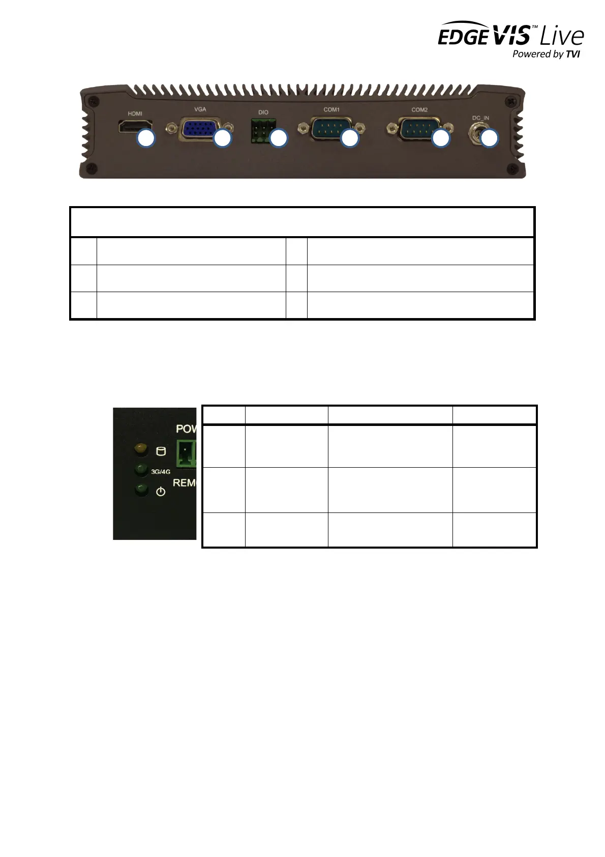
12V power input connector
Status indicators
The status LEDs on the top left of the front panel (see 9. in the front panel layout) provides visual feedback on device
status.
Powering the device and switching it on/off
The HD-IP150 must be powered using an AC/DC adapter (supplied). To switch the unit on simply connect the output
cable from the AC/DC adapter to the DC input connector on the back of HD-IP150 and connect the AC/DC adapter to
the mains power outlet. The unit can be remotely powered on/off by using a simple switch connected to the Remote
Power Switch Connector.
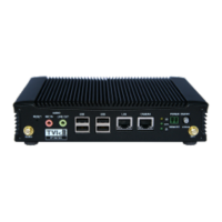
Connecting antennas for cellular and GPS connections
The front of the unit also includes antenna connectors for 3G/4G cellular modem and GPS. Antennas for each of these
are supplied with the HD-IP150.
HDD/SDD reading or writing
Modem powered, connected
and
transferring data
Modem powered
but not
transferring data