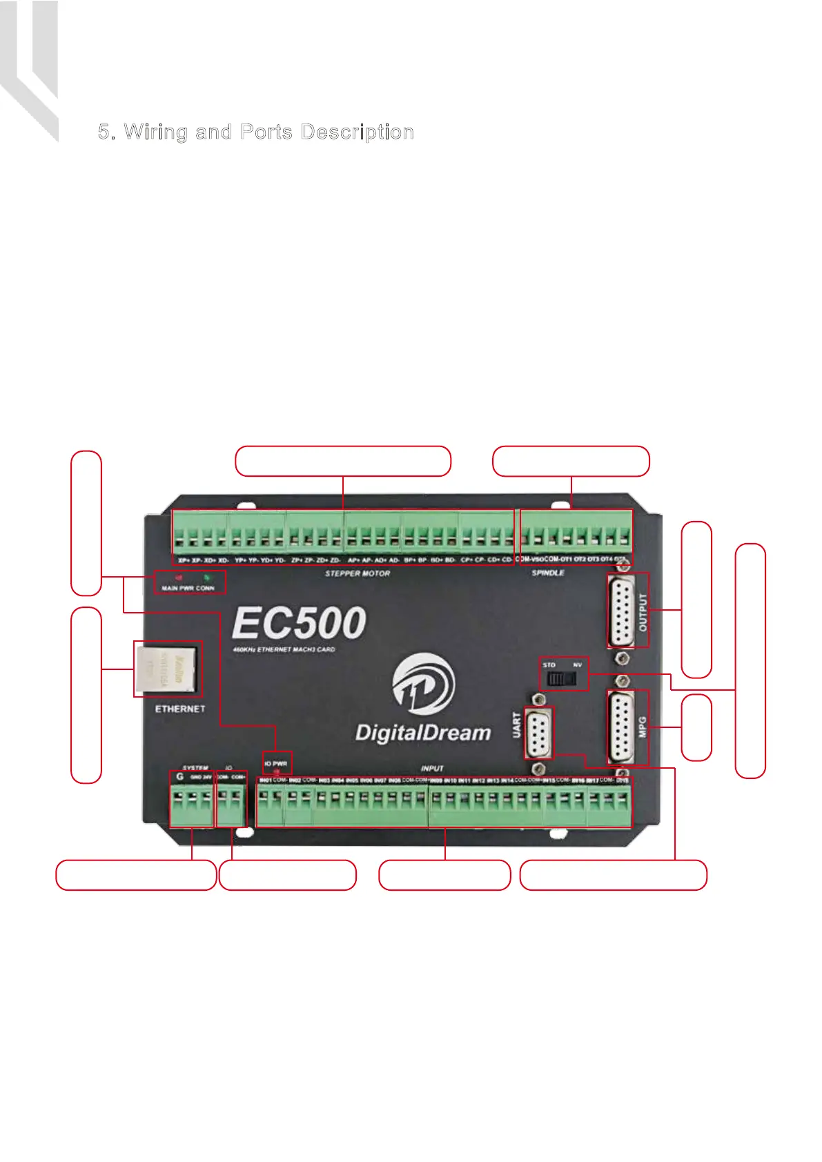
The following drawing shows the main connections of our device.We will descrip one by one in next
pages.Here are:
1 : Ethernet Communication Interface to PC
2 : Stepper/Servo motor Driver connection port
3 : Spindle Control Output Port
4 : Gerneral Output Interface
5 : MPG Port
6 : Functional Switch for MPG:Standard MPG or Digital Dream MPG
7 : Serial Extend Port
8 : Input Port:Limit/Home/Probe and so on
9 : IO Power Port
10 : Main Power Port
11 : Power and Communication LED Indicator
Picture 5-1 EC500 Wiring Over-view
10:Main Power Port
2: Stepper/Servo Driver
1: Ethernet Interface 11: LED Indicator
4: Genernal Output
9:IO Power Port
5: MPG
8:Input Port 7:Serial Extend Port
6: Optionanl Swirtch for MPG
3: Spindle Control
Page -4Digital Dream Mach3 Motion Controller EC500 User’s Manual
5. Wiring and Ports Description

 Loading...


