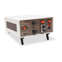
Operator's Manual DS7A - Constant Current Stimulator
Specifications
Stimulus Output
CURRENT Selected by 10 turn dial and x1/x10 switch
Dial reading 0.00 to 9.99 – DS7A
giving 0 to 10 mA (9.99 mA) for x1 setting – DS7A
and 0 to 100 mA (99.9 mA) for x10 setting - DS7A
Dial reading 0.00 to 99.9 – DS7AH
giving 0 to 100 mA (99.9 mA) for x1 setting – DS7AH
and 0 to 1000 mA (999 mA) for x10 setting - DS7AH
PULSE DURATION 50, 100, 200, 500, 1000, 2000 microseconds (µs) - DS7A
50, 100, 200 microseconds (µs) – DS7AH
PULSE POLARITY Three position toggle switch selects Normal/Reverse/Alternating.
COMPLIANCE Continuously variable from 100V to 400V
ON/OFF On is up
Off disables output and open circuits terminals
CONNECTIONS 4 mm shrouded sockets (red and black) on 3/4" centres
Red socket goes positive with reference to black socket
Trigger
The Maximum trigger rate is 1,000 pps (1 kHz).
INPUT Electrical via Rear Panel BNC socket:
Triggers : Logic signal (+3 to 15V) +ve edge,
TTL compatible (-ve edge by factory change).
Minimum Pulse Duration is 5 microseconds.
Front panel: Push button
Rear panel: 1/4" mono jack socket for foot switch.
(contact closure)
OUTPUT Rear panel BNC, positive TTL pulse,
1 ms (950 ±50µs) wide
(can be factory set for a negative pulse)
Indicators
TRIGGER LED - Amber, flashes for each trigger received
POLARITY LED – Green, two LEDs indicate the polarity of the next output pulse.
TOO-FAST LED – Amber, Lit when trigger frequency exceeds 100Hz in Alternating
Polarity Mode. Results in stimulus output being disabled and FAULT
condition (see below).
OUT OF COMPLIANCE LED - Amber, lit when selected current not delivered
Digitimer Ltd. 30 of 58 Copyright © 2014
File Ref: N:\Docs\Company\Manuals\DS7A\Issue-14\DS7A-iss14.odt Last Revised: February 1, 2017