Operator's Manual DS7A - Constant Current Stimulator
Trigger Polarity
These can be modified be moving jumpers mounted on the printed circuit board and MUST ONLY BE DONE
BY QUALIFIED PERSONNEL as high voltages exist internally.
The unit should be returned to the factory (or a qualified distributor) if Qualified Personnel are not available.
Instructions are available from the company to Qualified Personnel only.
Input trigger
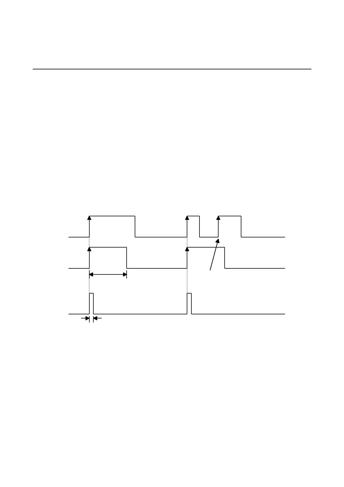
The DS7A is factory set to trigger from the positive going edge of an applied external signal which should be
between TTL (+5V) and +15V in amplitude and of at least 5 µs duration.
It can be changed so that the DS7A triggers from a negative going (from a positive voltage greater that
+3V, to zero volts) input.
The minimum voltage that is applied to this socket is -0.5V
The maximum voltage that is applied to this socket is +17V
Output trigger
A pulse of 1 ms (nominally) is produced in synchronism with the start of each stimulation pulse from the rear
panel BNC socket. It is factory set to be positive going TTL (+5V) which is normally at zero volts.
It can be changed to be normally at +5V going to zero volts for the duration of the pulse.
This shows the factory set Positive Trigger In & Trigger Out and 1 ms Trigger Out.
Digitimer Ltd. 34 of 58 Copyright © 2014
File Ref: N:\Docs\Company\Manuals\DS7A\Issue-14\DS7A-iss14.odt Last Revised: February 1, 2017