Operator's Manual DS7A - Constant Current Stimulator
Electrical characteristics of Triggers
Input options Manual front panel mounted push button.
Foot switch via rear panel socket.
Note that only Medical grade switches should be used, such
as the D185-FS1.
Logic signal (+3 to +15 V) +ve edge, TTL compatible
(-ve edge by internal change).
Output Positive TTL compatible signal 1 ms duration for recorder synchronisation.
(100 µs and/or active low by internal change).
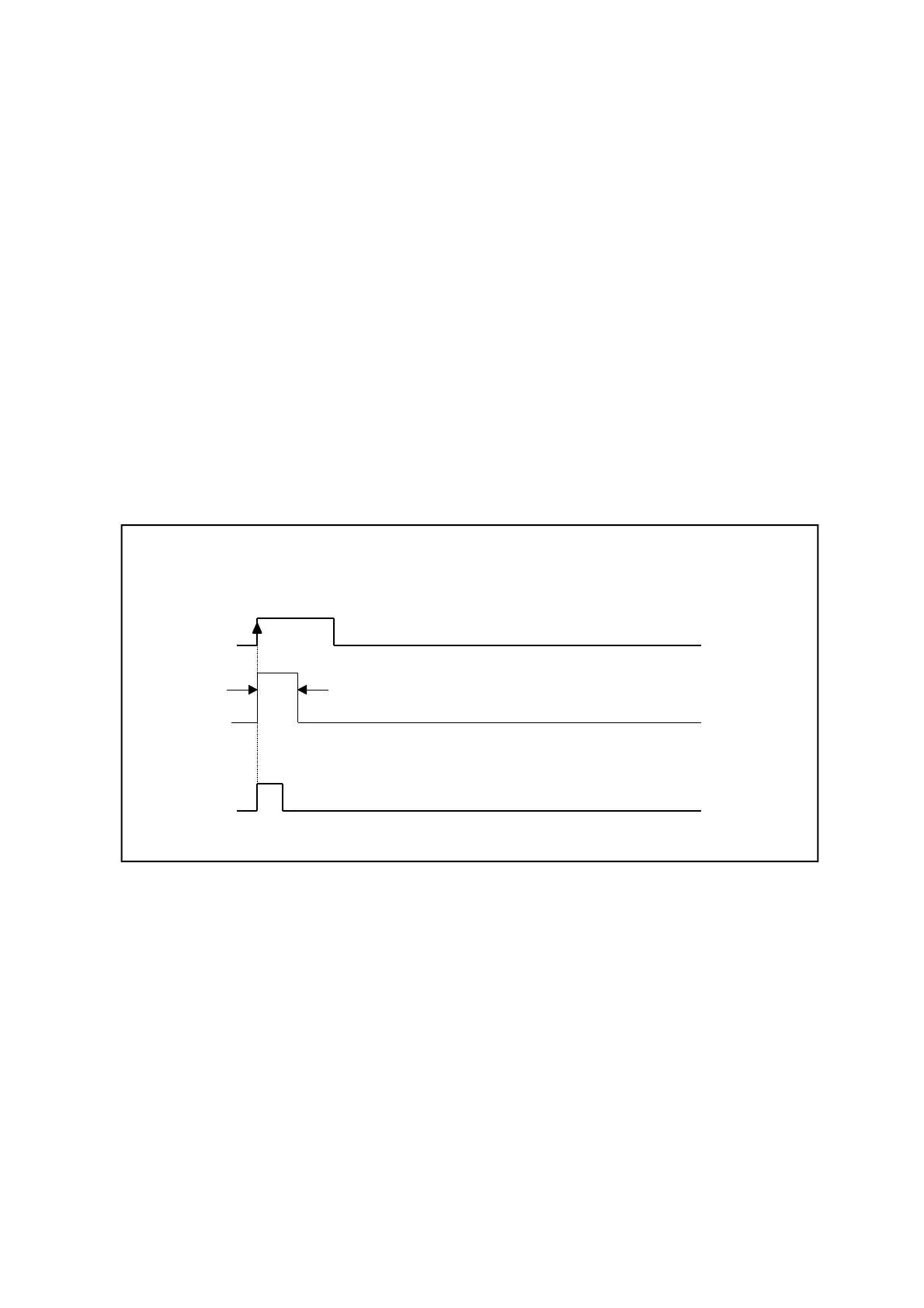
Trigger pulse to output stimulus relationship
An external Trigger-In, or front panel button or foot switch, will initiate a stimulus pulse, as indicated above,
without any delay.
The Trigger-Out signal will also be produced in synchrony with this signal.
Digitimer Ltd. 43 of 58 Copyright © 2014
File Ref: N:\Docs\Company\Manuals\DS7A\Issue-14\DS7A-iss14.odt Last Revised: February 1, 2017