Operator's Manual DS7A - Constant Current Stimulator
Appendix 3 .. Operational Tests
These tests are to be performed only by qualified personnel.
There should be no patient connection during these tests.
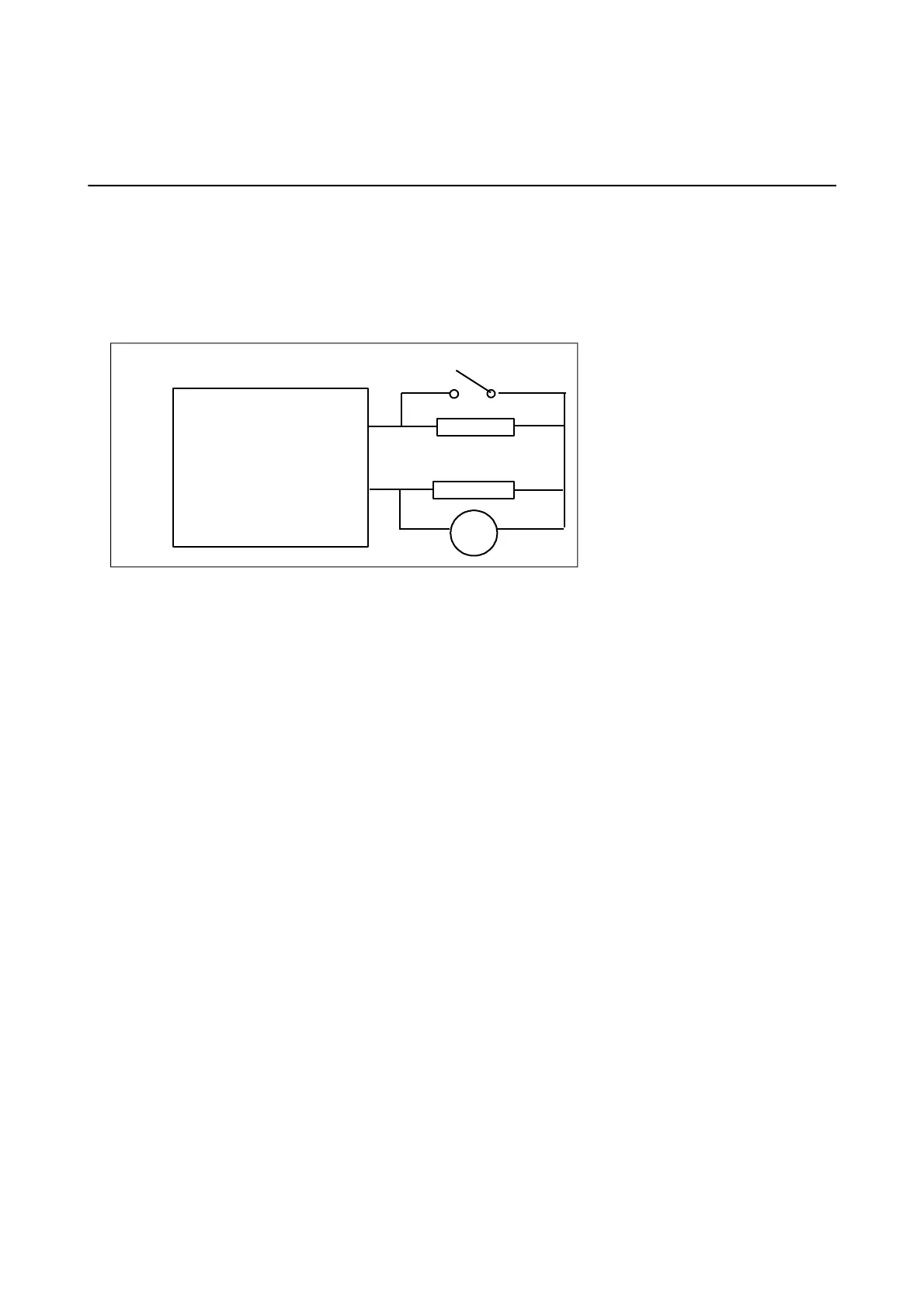
Connect a 100R resistor (1/2W) in series with a power resistor in the range 2000 to 3000 ohms (5 watts or
greater) across the output terminals. Monitor the potential across the 100R resistor. Note the 100R should
be connected to the positive terminal which is the common terminal of the oscilloscope monitor. See circuit
below.
Using a repetitive trigger (except for test 5) and pulse polarity set to “Normal” :
1. With SW1 open set voltage control to 400V, pulse duration 1000 microseconds and current control
to 100 mA (maximum CW, x10 range). Trigger DS7A and record stimulus output potential
generated across the 100R resistor - should be 10 volts peak, 1 ms wide. Check that the amber
"Trigger" indicator is turned on.
2. Now close SW1 and check that potential across 100R resistor has not changed appreciably.
3. With SW1 reopened reduce voltage control until potential across 100R resistor reduces. Check then
that the amber "out of compliance" indicator is turned on.
4. Now switch the current range from x10 to x1 and check that potential across 100R resistor falls from
10 volts peak to 1 volt peak.
5. Check that all three methods of triggering operate correctly.
a) Manual front panel switch
b) Foot switch through rear panel jack socket
c) Electrical pulse trigger through rear panel Trigger-In BNC socket.
6. Check that there is a Trigger Output pulse coincident with the stimulus pulse.
Digitimer Ltd. 49 of 58 Copyright © 2014
File Ref: N:\Docs\Company\Manuals\DS7A\Issue-14\DS7A-iss14.odt Last Revised: February 1, 2017