13
BAT+ Terminal
Battery interface
J4 Terminal
DC motor wire connection (Red wire to top, black wire to bottom)
J7 Terminal
1 Gate open control button (N.O.);
2 Gate close control button (N.O.);
3 Stop control button (N.O.);
4 Control button common terminal;
J8 Terminal
24V DC Alarm lamp
J10 Terminal
OP Open limit switch;
COM Limit switch common terminal;
CL Close limit switch;
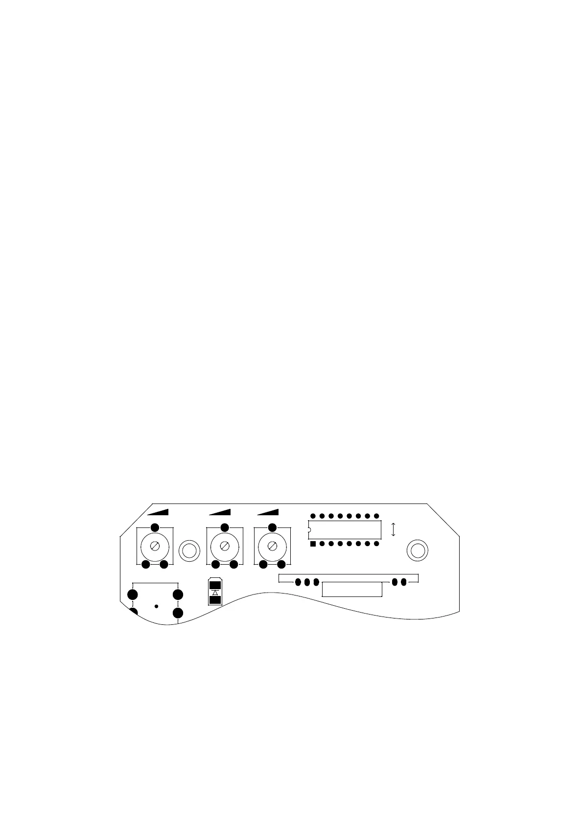
VR1VR1 VR2VR2 VR3VR3
U1U1
ONON
OFFOFF
J9J9
LRNLRN
K4K4
1 2 3 4 5
6
7
8
Figure 12
Adjusting knob
VR1: For motor working total time adjustment.
Clockwise rotation to increase, counter-clockwise rotation to reduce. The total time can
be set to 10 seconds as minimum and 90 seconds as maximum. For example, if gate