13
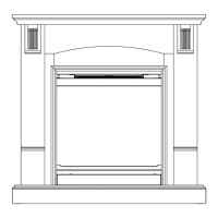
Installation
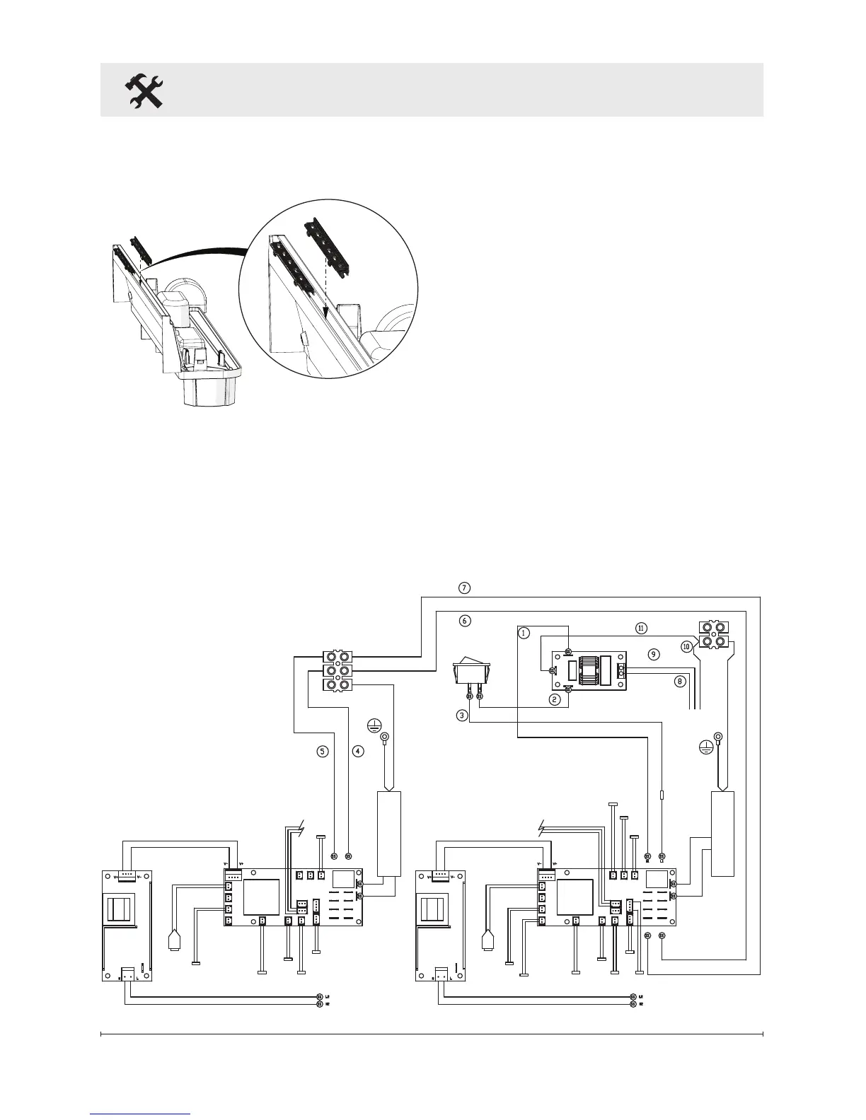
Wiring Diagram
Bathroom Installation
This unit must be protected by a
GFI circuit. If a receptacle is used it
must be readily accessible.
To prevent electrical shock this
unit is an electrical appliance
that is not watertight and must be
installed as to prevent water from
entering the unit. This unit must be
installed away from showers, tubs,
etc. Never locate replace over a
bathtub or other water containers.
Keep towels and
other combustible materials
3 feet (0.9 m) away from the top of
the unit.
Figure 6
TRANSDUCER 1
FUEL BED
SOLENOID
FILL1
TRANSDUCER 1
FUEL BED
SOLENOID
MAIN
SOLENOID
FILL1
2 WAY
REED
3 WAY
REED
SWITCH
BOARD
LED
DRIVER
BOARD
2 WAY
REED
BT
RECEIVER
LED
DRIVER
BOARD
RELAYRELAY
N1
N2
N3
N4
L1
N1
24V INPUT 24V INPUT
L1
L2
L3
L4
N1
N2
N3
N4
L1
L2
L3
N3 L3
L4
HEAT
CONTROL PCB
SPEAKER
BLUE
WHITE
BLACK
GREEN / YELLOW
BROWN
DC FAN
MOTOR
DC FAN
MOTOR
COMMUNICATION LINK
ELEMENT
ELEMENT
3 WAY
REED
SWITCH
BOARD
CDFI500-PRO