6 www.dimplex.com
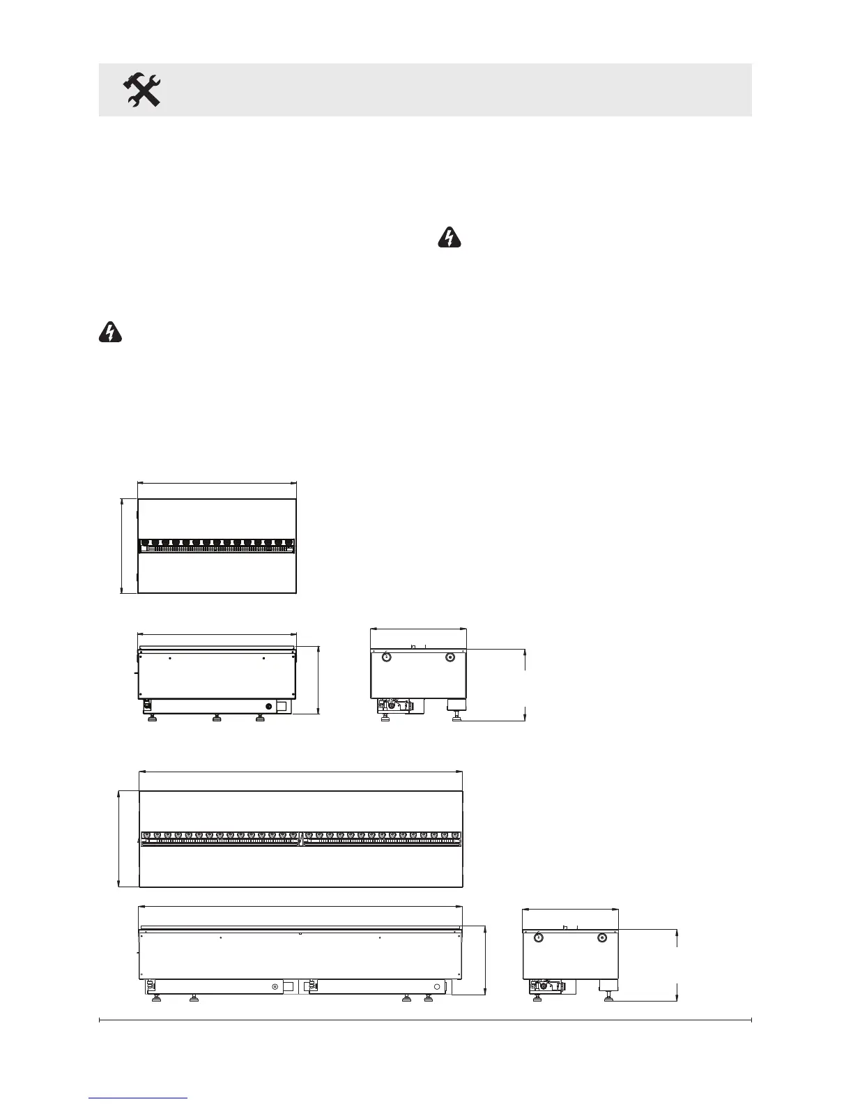
8.50 in. (216 mm)
40.08 in. (1018 mm)
Logset: 13.94 in. (353 mm)
11.94 in. (303 mm)
40.08 in. (1018 mm)
Media Plate: 11.94 in. (303 mm)
8.50 in. (216 mm)
20.04 in. (509 mm)
20.04 in. (509 mm)
11.94 in. (303 mm)
Logset: 13.94 in. (353 mm)
Adjustable from
9.13 in. (232 mm)
to 9.63 in. (245 mm)
Media Plate: 11.94 in. (303 mm)
CDFI1000P
CDFI500P
Adjustable from
9.13 in. (232 mm)
to 9.63 in. (245 mm)
Installation
The CDFI1000-PRO and
CDFI500-PRO are supplied in an
assembled state and are designed
to be permanently installed. The
units come ready for hardwire
installation and the use of the
water rell containers.
WARNING: Construction and
electrical outlet wiring must
comply with local building codes
and other applicable regulations
to reduce the risk of re, electric
shock and injury to persons.
WARNING: To reduce the risk of
re, do not store or use gasoline
or other ammable vapours or
liquids in the vicinity of the unit.
!
NOTE: A 15 Amp, 120 Volt
circuit is required. A dedicated
circuit is preferred but not essential
in all cases. A dedicated circuit will
be required if, after installation,
the circuit breaker trips or the fuse
blows on a regular basis when the
cassette is operating. Additional
appliances on the same circuit may
exceed the current rating of the
circuit breaker.
!
NOTE: When prepar-
ing the opening for the unit
¼ in. (6.4 mm) of clearance
should be maintained from
each surface to ensure easy
installation.
Product Dimensions
CDFI500-PRO
CDFI1000-PRO