8 www.dimplex.com
!
NOTE:
pry between the end of the connector and the switch to
release the wires.
Remove the thermostat control knob by pulling straight 7.
out.
Remove the 2 mounting screws and replace the old 8.
thermostat with the new one.
Reassemble in the reverse order as above.9.
FLICKER ROD/MOTOR REPLACEMENT
Tools Required:
CAUTION: If unit was operating prior to servicing allow
at least 10 minutes for lights, heating elements and top
panel to cool off to avoid accidental burning of skin.
WARNING: Disconnect power before attempting any
maintenance to reduce the risk of electric shock or damage
to persons.
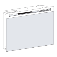
Open the front control cover.1.
Remove front glass by removing the 2 outer screws 2.
Remove the log grate by removing the 4 mounting 3.
Remove the log set by lifting straight up. 4.
5.
being careful not to damage any of the wiring.
-6.
ing the end of the rod to the left and separating it from
the rubber sleeve.
Remove the rubber sleeve from the motor shaft.7.
8.
block, noting their original locations
Remove the 2 motor mounting screws and remove the 9.
10.
Reassemble in the reverse order as above11.
Tools Required:
CAUTION: If unit was operating prior to servicing allow
at least 10 minutes for lights, heating elements and top
panel to cool off to avoid accidental burning of skin.
WARNING: Disconnect power before attempting any
maintenance to reduce the risk of electric shock or damage
to persons.
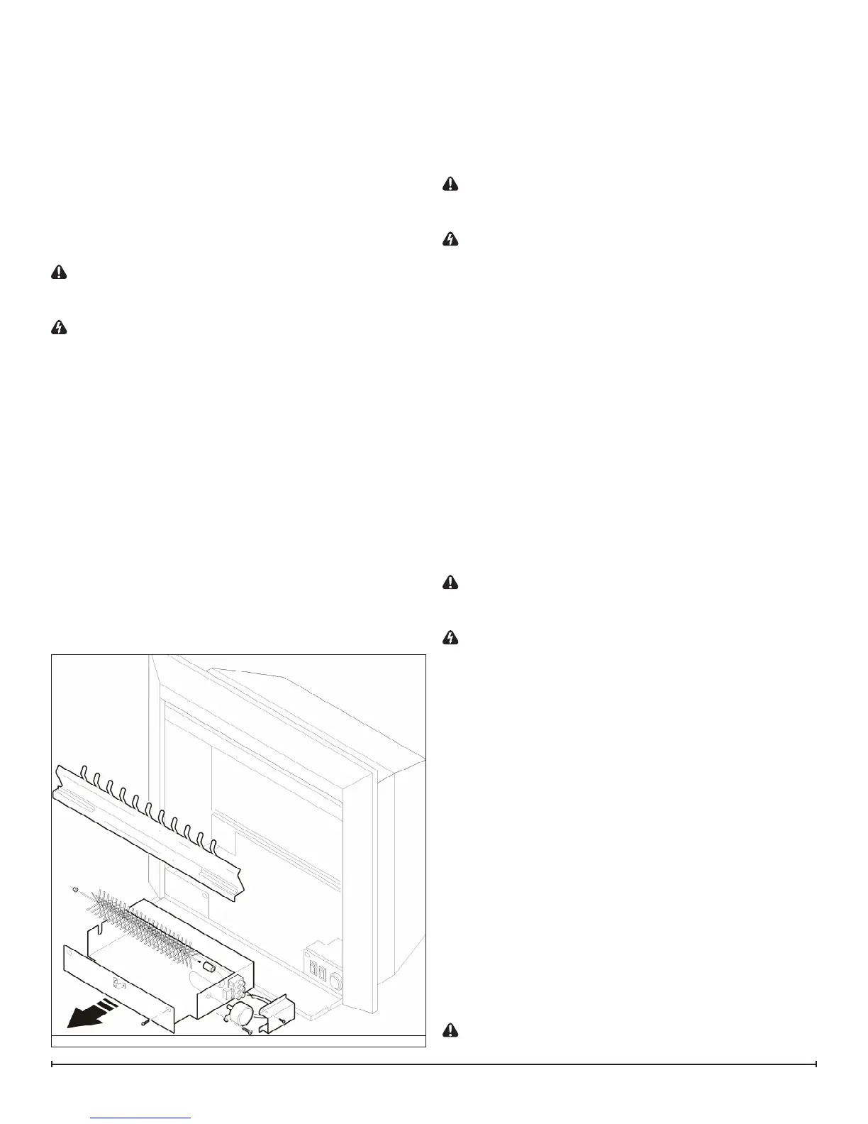
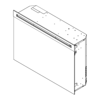
Remove the 4 retaining screws and lift the top cover off 1.
of the insert being careful not to damage the wiring.
Remove the 4 heater mounting screws from the top of 2.
the top cover to separate the heater assembly.
Remove the 2 heater mounting brackets from the 3.
heater assembly.
Disconnect the 2 heater switch leads from the heater 4.
noting their original locations.
Disconnect the thermal cut-out wire from the wire nut.5.
Reassemble in the reverse order as above, with the 6.
new component.
REMOTE CONTROL RECEIVER
REPLACEMENT
Tools Required:
CAUTION: If unit was operating prior to servicing allow
at least 10 minutes for lights, heating elements and top
panel to cool off to avoid accidental burning of skin.
WARNING: Disconnect power before attempting any
maintenance to reduce the risk of electric shock or damage
to persons.
Remove the 4 retaining screws and lift the top cover 1.
off of the insert being careful not to damage the wiring.
Disconnect the wire connections from the circuit board 2.
noting their original locations.
!
NOTE:-
tly pry between the end of the connector and the receiver
board to release the wires.
3.
on the circuit board by grasping with pliers and twisting
on the protruding part of the stud, push the remainder
of the studs out through the top panel.
!
NOTE: New mounting studs are supplied with the
replacement circuit board.
Properly orient the new circuit board and reconnect all 4.
of the wiring connections.
POWER CORD REPLACEMENT
Tools Required:
CAUTION: If unit was operating prior to servicing allow
Figure 8