8 www.dimplex.com
1. Follow “Component Access” instructions before pro-
ceeding.
2. Locate the On/Off switch and disconnect the wiring
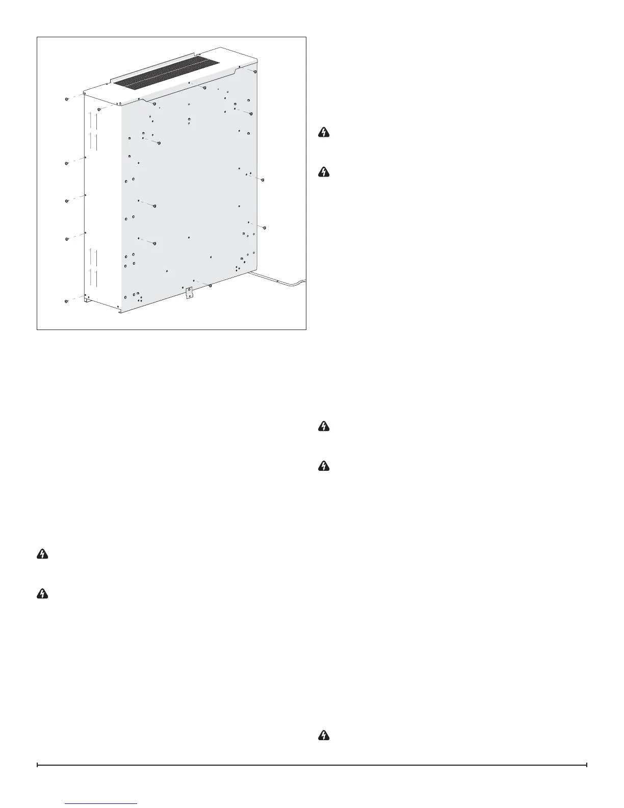
connections noting their original locations. (Figure 8)
!
NOTE: A at head screwdriver can be used to gently
pry between the end of the connector and the switch to
release the wires.
3. Depress the retainer clips on the rear of the switch and
push the switch out through the opening.
4. Properly orient and insert the new switch and connect
all of the wiring.
5. Reassemble in the reverse order as above.
3 POSITION SWITCH REPLACEMENT
Tools Required: Philips head screwdriver
Flat head screwdriver
WARNING: If the replace was operating prior to ser-
vicing, allow at least 10 minutes for light bulbs and heating
elements to cool off to avoid accidental burning of skin.
WARNING: Disconnect power before attempting any
maintenance to reduce the risk of electric shock or damage
to persons.
1. Follow “Component Access” instructions before pro-
ceeding.
2. Locate the 3 Position switch and disconnect the wiring
connections noting their original locations. (Figure 8)
!
NOTE: A at head screwdriver can be used to gently
pry between the end of the connector and the switch to
release the wires.
3. Depress the retainer clips on the rear of the switch and
push the switch out through the opening.
4. Properly orient and insert the new switch and connect
all of the wiring.
5. Reassemble in the reverse order as above.
THERMOSTAT REPLACEMENT
Tools Required: Philips head screwdriver
Flat head screwdriver
WARNING: If the replace was operating prior to ser-
vicing, allow at least 10 minutes for light bulbs and heating
elements to cool off to avoid accidental burning of skin.
WARNING: Disconnect power before attempting any
maintenance to reduce the risk of electric shock or damage
to persons.
1. Follow “Component Access” instructions before pro-
ceeding.
2. Locate the thermostat and disconnect the wiring con-
nections noting their original locations. (Figure 8)
!
NOTE: A at head screwdriver can be used to gently
pry between the end of the connector and the board to
release the wires.
3. Remove the screws securing the thermostat to the
chassis and gently lift the thermostat off.
4. Properly orient and install the new thermostat and con-
nect all of the wiring.
5. Reassemble in the reverse order as above.
POTENTIOMETER REPLACEMENT
Tools Required: Philips head screwdriver
Flat head screwdriver
WARNING: If the replace was operating prior to ser-
vicing, allow at least 10 minutes for light bulbs and heating
elements to cool off to avoid accidental burning of skin.
WARNING: Disconnect power before attempting any
maintenance to reduce the risk of electric shock or damage
to persons.
1. Follow “Component Access” instructions before pro-
ceeding.
2. Locate the potentiometer and disconnect the wiring
connections noting their original locations. (Figure 8)
!
NOTE: A at head screwdriver can be used to gently
pry between the end of the connector and the board to
release the wires.
3. Remove the screws securing the potentiometer to the
chassis and gently lift the potentiometer off.
4. Replace the control knob, if required.
5. Properly orient and install the new potentiometer and
connect all of the wiring.
6. Reassemble in the reverse order as above.
REMOTE RECEIVER REPLACEMENT
Tools Required: Philips head screwdriver
Flat head screwdriver
WARNING: If the replace was operating prior to ser-
vicing, allow at least 10 minutes for light bulbs and heating
Figure 7