12 www.dimplex.com
WARNING: Disconnect power before attempting any
maintenance or cleaning to reduce the risk of electric
shock or damage to persons.
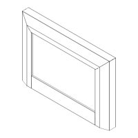
Remove the rebox trim by inserting a slotted screw-1.
driver and turning ¼ of a turn to release the trim from
the rebox.
Remove rebox from the mantel.2.
Remove front glass retaining clip, while holding the 3.
front glass.
Remove the front glass and set aside.4.
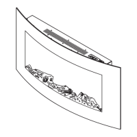
Remove the log set by lifting up the front edge of the 5.
log until it clears the front tabs. (Figure 7)
Pull out until the rear tab clears the back ledge, then lift 6.
out.
Cut the icker motor wires close to the icker motor 7.
end with wire cutters.
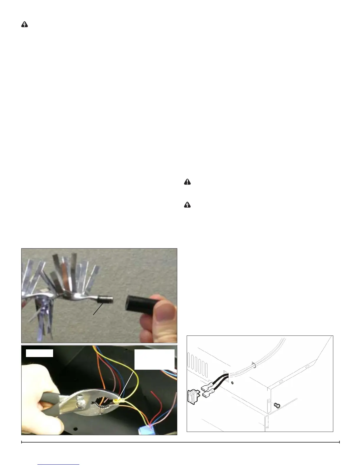
Remove the reector rod from the icker motor by pull-8.
ing the end of the rod to the left and cut the reector
spring with wire cutters. (Figure 12)
!
NOTE: DO NOT TAKE THE LEFTOVER SPRING OFF
THE END OF THE REFLECTOR ROD.
Remove the 2 screws securing the icker motor to the 9.
icker motor bracket.
Discard the old icker motor.10.
Pick up the 1 ½” rubber sleeve and locate over remain-11.
ing spring on reector rod.
!
NOTE: BE SURE TO LOCATE THE LARGE OPEN-
ING OF THE RUBBER SLEEVE OVER THE REMAINING
SPRING OF THE REFLECTOR ROD.
Pick up new icker motor and cut wire leads to 3 ½” 12.
long with wire cutters.
Secure new icker motor to the existing reector rod. 13.
Ensure the icker motor bracket is in between the mo-
tor and the reector rod.
Pick up slip joint pliers and adjust to proper slot.14.
Pick up 3M wire connector and place 1 yellow wire into 15.
each terminal - total of 2 yellow wires. (Figure 13)
Secure wire connector by crimping the 3M symbol with 16.
slip joint pliers.
Pull on end of wires to ensure a strong connection.17.
Repeat this process for the 4 remaining wires (red, 18.
blue, orange, grey).
Install the new icker motor in place of the old one.19.
Reassemble in the reverse order.20.
HEATER ON/OFF SWITCH
Tools Required: Phillips head Screwdriver
Flat Head Screwdriver
CAUTION: If the replace was operating prior to ser-
vicing allow at least 5 minutes for light bulbs and heating
element to cool off to avoid accidental burning of skin.
WARNING: Disconnect power before attempting any
maintenance or cleaning to reduce the risk of electric
shock or damage to persons.
Remove the rebox trim by inserting a slotted screw-1.
driver and turning ¼ of a turn to release the trim from
the rebox.
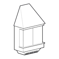
Remove the rebox from the mantel.2.
Lower the grille covering the controls.3.
Remove the retaining screws on the top cover and 4.
remove the top, being careful not to damage any of the
wiring.
Locate the Heater On/Off switch mounted on the top 5.
panel and disconnect the wiring clips and connections
noting their original locations.
!
NOTE: Using a at head screwdriver, gently pry be-
tween the end of the connectors and the switch to release
the wires.
Figure 12
Remaining Spring
on Rod
Figure 13
Ensure that all
connectors have
two wires with the
same color
Figure 14