10 www.dimplex.com
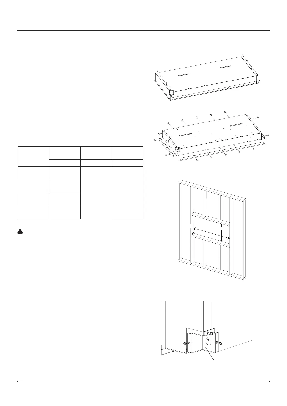
Recessed Installation
Installation
Electrical Cover
1. Remove the side cover panels from the replace by
removing the 5 screws on each of the cover panels
(4 on the back of the replace, 1 on the bottom).
(Figure2)
2. If a trimless installation is desired, remove pre-
installed trim by removing the screws (number of
screws will vary by model). (Figure 3)
!
NOTE: The pre-installed trim helps conceal
imperfections in the drywall edges against
the replace and gives the replace a nished
appearance.
3. Prepare a framed opening, following the dimensions in
the table below. (Figure 4)
Framing Dimensions
Model
Width Height
Depth*
(mininum)
A B C
PLF3614-XS
37"
940 mm
19"
483 mm
4"
102 mm
* Includes
½" drywall
PLF4214-XS
43"
1092 mm
PLF5014-XS
51"
1295 mm
PLF6014-XS
61"
1549 mm
CAUTION: This replace is NOT load-bearing. Ensure
the opening for the replace is framed in such a way
that the weight of the building materials will not create
pressure on the top of the replace.
!
NOTE: Wiring is performed at the bottom right back
corner of the rebox. (Figure 5) Plan the framing to
allow routing the power cable to this location.
4. Install and nish drywall as desired.
5. Remove the 3 screws that secure the electrical cover
to complete the wiring. (Figure 5)
6. Complete the wiring according to instructions in the
Electrical Installation section (pp. 12-13). Reinstall the
electrical cover after wiring is complete.
7. Lift the rebox into the opening in the framing.
8. Level the rebox. A bubble level is included in the
hardware kit provided.
Figure 2
Figure 3
Figure 4
Figure 5
C
A
B