8 www.dimplex.com
Opti-V Installation
2. Allow up to 4 ft. (121.9 cm) of
service cable for connecting a
power supply wire to the cable
clamp on the Opti-V when
installing before nishing wall.
!
NOTE: A 15 amp, 120 volt
alternating current (VAC) circuit
is recommended, but the unit is
constructed that it can operate
using voltages from 120-
240VAC.
!
NOTE: Use minimum 14 AWG
supply cable with two insulated
copper conductors (white and
black) and one bare ground
wire. Do not use cable with
aluminum conductors.
!
NOTE: It is recommended
that all drywall installation and
nishing be completed after
unit is fully installed.
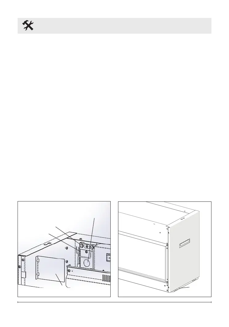
3. In the upper left hand corner
of the unit, loosen the two
securing screws and remove
the electrical cover panel.
(Figure 2)
4. Install a ⅜ in. (10 mm) or ½ in.
(13 mm) cable connector, not
included, suitable for mounting
in a ⅞ in. (22 mm) hole, to
the cable plate and feed the
supply cable through the
connector and secure.
5. Place the unit in the framed
opening, level with shims if
necessary and attach unit to
frame using mounting anges
provided (Figure 3).
Figure 2
Electrical
Cover Panel
Cable Clamp
Hole
Figure 3
Mounting
Flanges
Cable Plate
Grounding
Screw