1. Place the heater within its packaging • at on the ground with arrows printed on the base of
the carton pointing upwards.
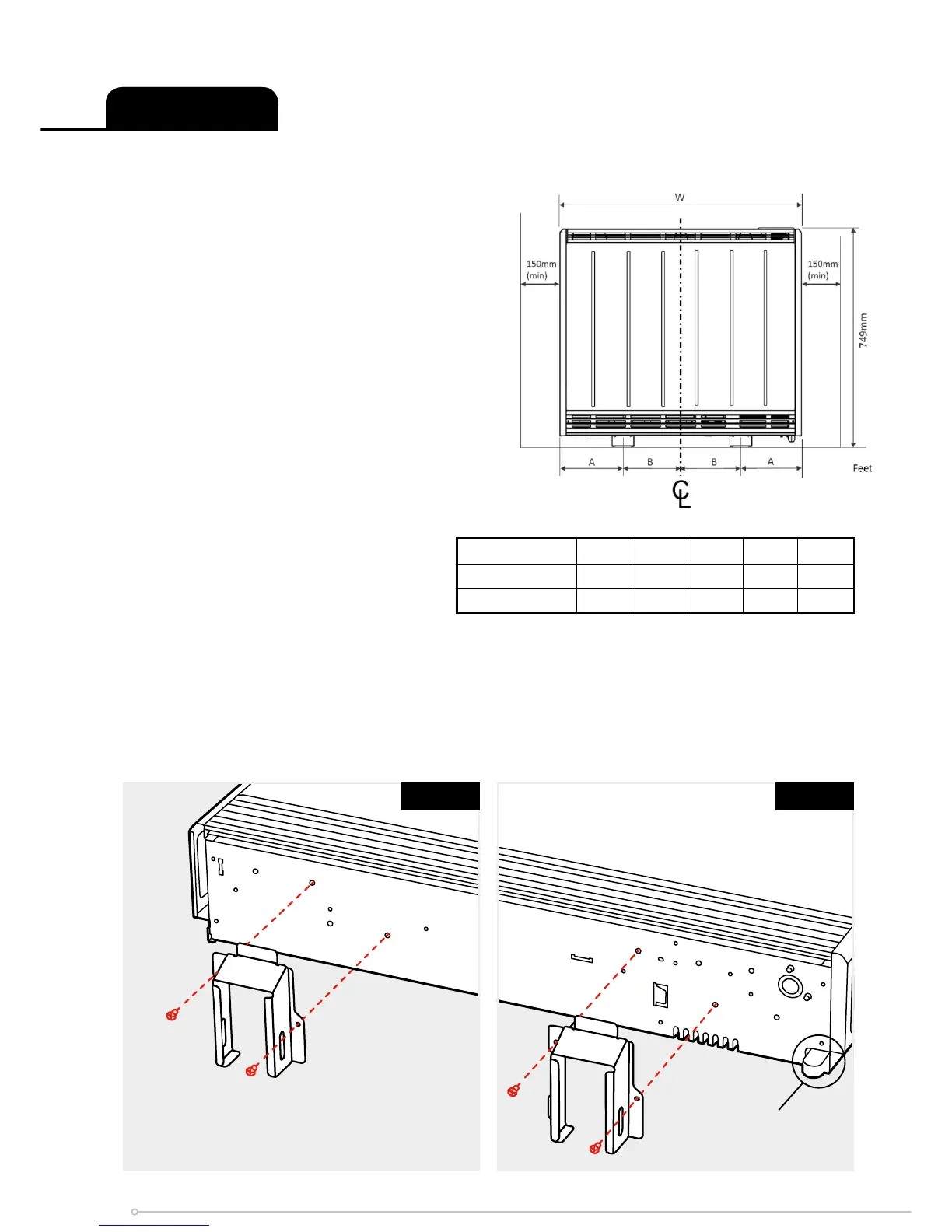
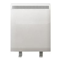
2. Feet are fi tted in the default position (X position)
and can be moved to the outside position
(Y position) if necessary. (Fig. 1a and Fig.
1b). NB: Repositioning of feet may be
required depending on fl oor arrangement
(e.g. replacing an installation).
Stand the heater on its feet before removing the
packaging.
CAUTION SHOULD BE TAKEN NOT TO
REST THE HEATER UPON THE ROOM
TEMPERATURE SENSOR HOUSING. (Fig. 1b)
Dispose of packaging in an appropriate way.
Read these instructions carefully before
proceeding any further with the installation.
3. Ensure the heater is stable before
removing the screws which hold
the bottom grille panel in position.
(Fig. 2) Set the bottom grille to one
side, avoiding its sharp edges when
handling.
4. Remove the two screws securing the front panel, located at the bottom of the heater
(Fig. 3). Once removed set carefully to one side to avoid damage.
NOTE - Retain these screws for reassembly. If misplaced, M4 x 10 Triptap screws must
be used.
IMPORTANT - Do not use the outer top panel or the rear heat shield to lift or carry the heater.
Preparation
Fig. 1bFig. 1a
Y
Y
X
X
Room Sensor
Housing
Models XLE050 XLE070 XLE100 XLE125 XLE150
Feet Position 1 ‘A/B’ 167/124 167/185 167/246 160/314 160/375
Feet Position 2 ‘A/B’ 93/198 93/259 93/320 100/374 100/435
6