Standstill and speed monitoring
Original instruction manual Date: 2017.08.28 Page 12 of 28
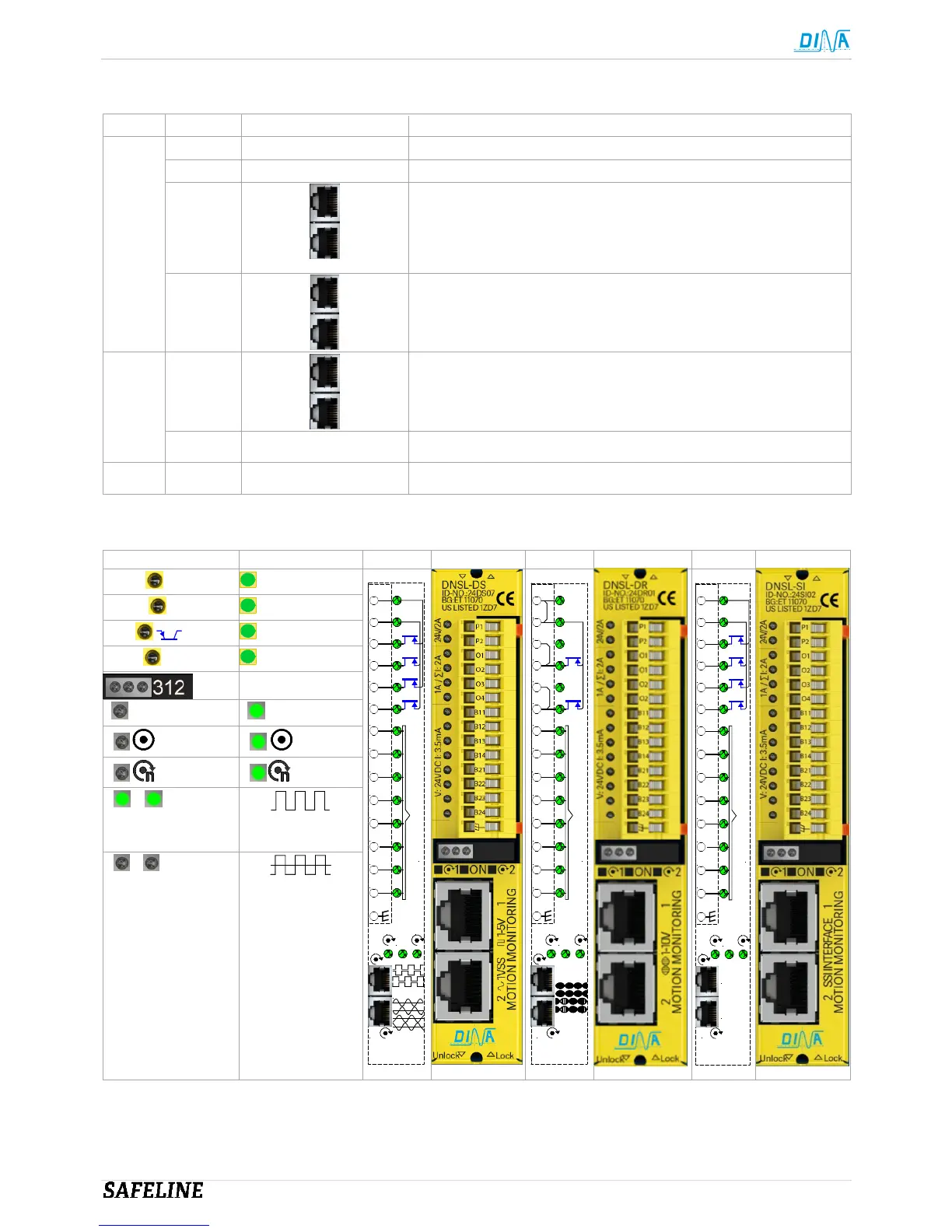
7 Standstill and speed monitoring
DNSL- ID-No.: Terminals/ connectors
Safe digital inputs for safety functions
all
DS 24DS07
2 safe monitoring for standstill, speed, position, direction and
brake in different function modes
Sin/cos or TTL measuring systems, HTL signals via HTL cable
adapter
DR 24DR01
2 safe monitoring for standstill, speed, position, direction and
brake in different function modes
Resolver Measuring system
SI 24SI02
2 safe monitoring for standstill, speed, position, direction and
brake in different function modes
SSI interface Measuring system
DS/ SI O1-O4 Semi-conductor outputs configurable as safe or clock outputs
DR O1-O2 Semi-conductor outputs configurable as safe or clock outputs
7.1
Schematic, display and front view
Display DNSL-DS
Signal=24V
DNSL-DS
ON
P1 24VDC
P2 24VDC
O1
O2
O3
O4
B11
B12
B13
B14
B21
B22
B23
B24
1 2
oder/or
Eingänge/ Inputs
1
2
DNSL-DR
ON
P1 24VDC
P2
O1
O1
O2
O2
B11
B12
B13
B14
B21
B22
B23
B24
1 2
Eingänge/ Inputs
1
2
DNSL-SI
ON
P1 24VDC
P2 24VDC
O1
O2
O3
O4
B11
B12
B13
B14
B21
B22
B23
B24
1 2
Eingänge/ Inputs
1
2
SSI 1
SSI 2
Signal=24V
O1-4 I=0
I>0 ≤ max.
P1/P2 O-Pwr = 0V
1 Pwr: 0V* 1 Pwr: 24V*
2 n>0 2 n=0
3 n>max. 3 n<max.
2 3
Measuring
OK
2 3
No
measuring system
See also Designer instruction manual.
 Loading...