Product description
Original instruction manual Date: 2017.08.28 Page 8 of 28
3 Product description
• SAFELINE is appropriated to be used in machines and plants to protect the operator against potential
dangers and plants against destruction.
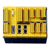
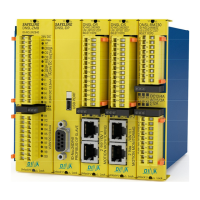
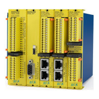
• SAFELINE is housed in a metal rack. It can be mounted by spring fasteners to a DIN rail.
• The individual modules are pluggable. The number of the used modules set the rack width. Up to 15 modules
can be used.
• Racks with 2, 3, 5, 7, 9, 13 and 15 slots are available.
• Unused slots are closed with a blind cover. ID-No.: 10BD00
• All modules are connected by 2 backplane bus system.
• To fulfil the requirements of the wide ranges of needs different modules with diverse functions are available.
• SAFELINE is deliverable with different field bus modules.
• A variety of safe functions are available such as logic modules, timers, safety circuits, mode selector,
generator, counters, comparators, feedback, restart interlock etc.
• A lot of safe digital and analogue inputs, safe semi-conductor outputs and contact outputs are available.
• Semi-conductor outputs are overload and short circuit proofed.
• The switching status of all I/O terminals and supply voltage are indicated by LED.
• The power supply (24V DC) is connected to the terminals A1/ A2 at the central module for all modules.
• To supply the semi-conductor outputs at the function modules with 24V DC the terminal P is designated.
• The user application is configurable with the SAFELINE Designer on a PC. The application is transferred by
the USB or V24 interface at the central module. The Designer is software developed by DINA.
• The user application, instruction manual, Designer and all other documents can be stored on a memory
medium, if a central module with an USB interface is used.
• The Medium is to use as a drive.
• The used connection cable with COM PORT interface is V24 (1:1). Pins 2, 3 and 5 are only important.
• Remark
• The function devices are tested safe and certificated as a part of the firmware.
• A modification of the certified function devices as part of the firmware is excluded.
o Behaviour with errors
• Output O1 at the central module is switching off.
• Correction Inspection of the wiring and assembly
• Switching off and on of the power clears the errors. See also diagnostics tool at the Designer
 Loading...