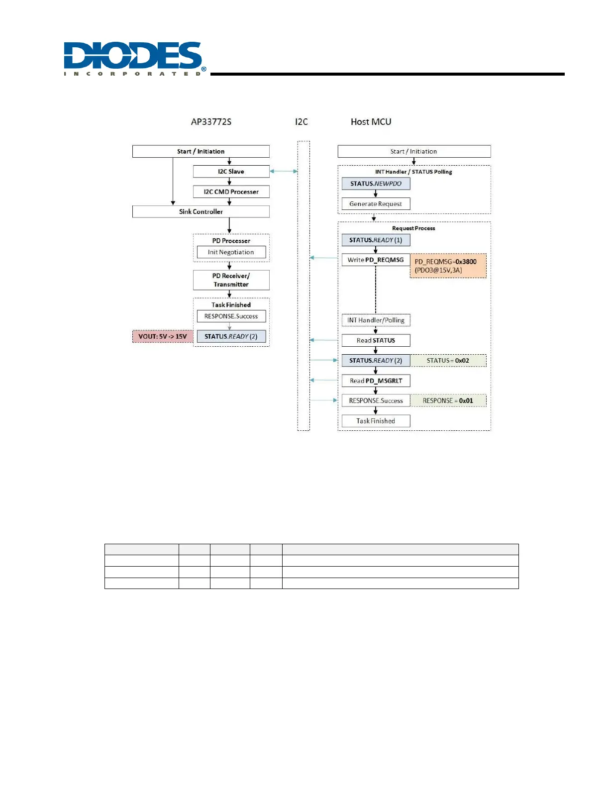
8.3 Request Process
For example, on the energy-sourcing side, the system uses a USB PD3.1 compliance charger (PDC) rated at 60W output power
(5V/9V/15V/20V@3A). For the energy-sinking side, a battery-powered Type-C mobile device adopts the AP33772S as the USB PD3.1 Sink
compliance controller. The host appliance requests 45W power at 15V@3A input and starts charging after successful negotiation.
Based on the TCD requirements and the source capabilities obtained by reading the SRCPDO register, the host MCU selects the required
PDO_INDEX, CURRENT_SEL, and VOLTAGE_SEL to generate the request message (PD_REQMSG).
After the AP33772S startup process is completed (STATUS.READY=1), the host MCU can initiate the request process through the I2C
interface. Here, PD_REQMSG is written to 3800h to request 45W power at 15V@3A. The request parameters are described in the following
table.
When receiving the PD_REQMSG command, the AP33772S will initiate negotiation with the PD source according to the requirements of the
host MCU. After the PD negotiation is completed, and if the AP33772S receives a PS_RDY message from the PD source, the device sets the
PD_MSGRLT.RESPONSE parameter to 1 (Success). Then, the VOUT voltage transitions from 5V to 15V.
Finally, the STATUS.READY flag is set to 1, indicating that the request process is completed and the host MCU can send other
requests/commands thereafter.
Therefore, the host MCU should handle the INT signal or poll STATUS to obtain the status of the AP33772S in real time.
1. STARTED = 1, the host MCU can disable/enable specific modules by writing MASK, CONFIG, PDCONFIG, and VSELMIN registers at
startup.
2. NEWPDO = 1, the host MCU should read the SRCPDO register to obtain the latest PD source capabilities, and then search for the
appropriate PDO again.
3. READY = 1, the host MCU can send requests/commands or read/write any register through the I2C interface.
4. After writing to the PD_REQMSG register, the host MCU should wait for the STATUS.READY flag to be set high and then read the
PD_MSGRLT register to obtain the negotiation result.
 Loading...