AP33772S I2C USB PD Sink Controller
EVB User Guide
AP33772S EVB User Guide
Rev. 2.0
July 2024
© 2024 Copyright Diodes Incorporated. All Rights Reserved.
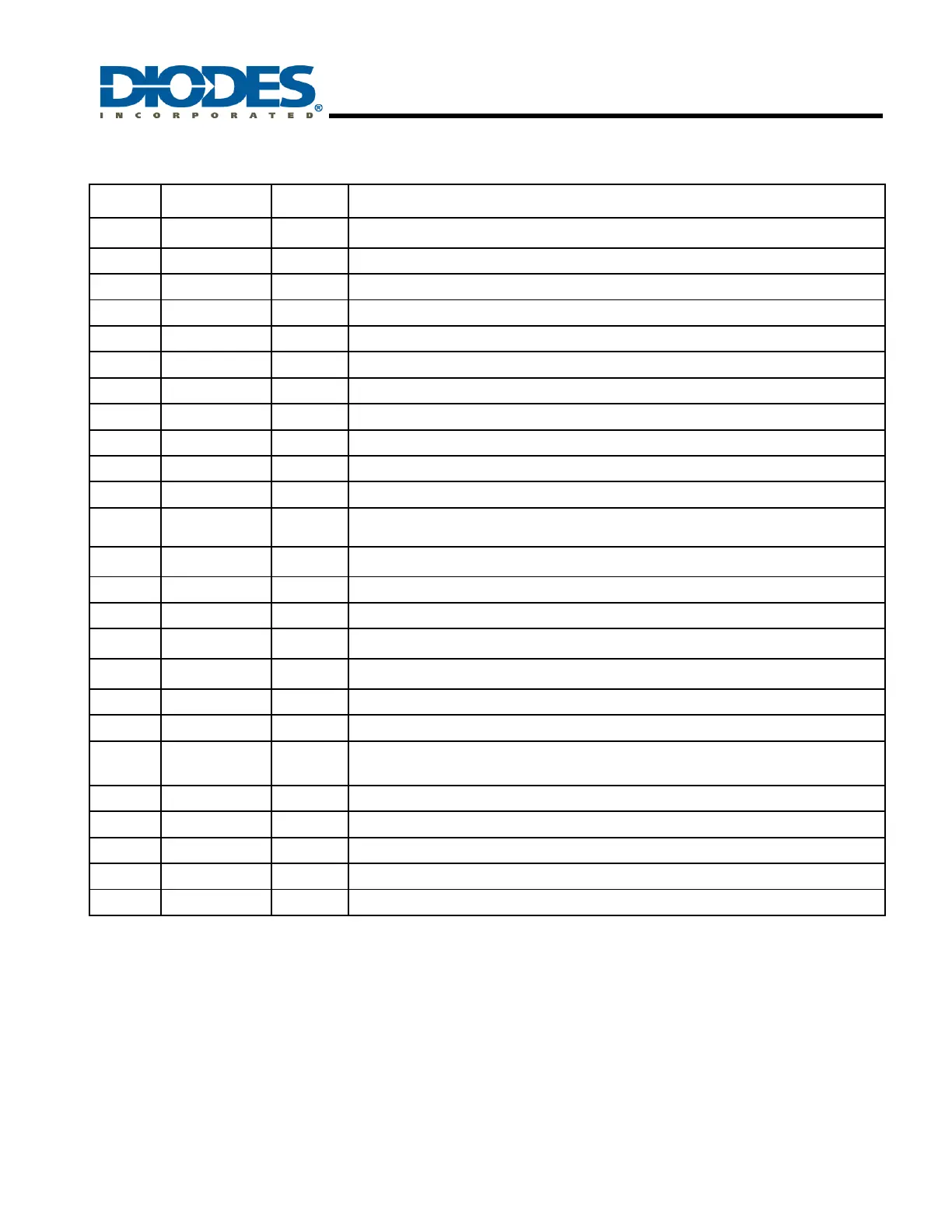
Current Sense Positive Node, connect to the positive node of the external current sensing
resistor
I2C Data, need to be pulled up externally
I2C Clock, need to be pulled up externally
Flip indicator of Type-C plug. LOW: CC1 detected; HIGH: CC2 detected
LED Indicator Pin, refer to Table 13 for detailed description
Interrupt pin is used to inform external MCU. LOW: normal; HIGH: interrupt occured
1.8V LDO output for internal use only. Connect a 100nF cap to GND. This pin cannot drive
external load.
100uA Current Source output for NTC connected to ground; this NTC is used to monitor
temperature variation
For current measurement, a 100nF cap to Ground is suggested
Type-C Configuration Channel 2 (CC2); the CC2 pin detects, configures, and manages the
connections across a USB Type-C cable
Type-C Configuration Channel 1 (CC1); the CC1 pin detects, configures, and manages the
connections across a USB Type-C cable
Output of the internal LDO with VCC as input; a 1μF cap is required to connect this pin to GND.
When VCC is off, V5V pin can be an alternative power path for the AP33772S when provided
with a 5V external power.
Terminal for VOUT monitoring
NMOS Switch gate control to switch the NMOS on or off
The power supply of the IC; a 1μF cap is required to connect this pin to GND pin
Exposed pad is suggested to connect to Ground for improved thermal dissipation
Table 1 – Pin Descriptions of the AP33772S PD Sink Controller
Notes:
AHV – Analog High Voltage pin
AP – Power for Analog Circuit and Analog I/O pins, 5.0V operation
AI – Analog Input pin
DP – Power for Digital Circuit operation
AIO – Analog I/O pin with 5.0V operation; CC1/CC2 pins are 3.3V operation
DIO – Digital I/O pin; all are 5.0V operation
DI – Digital input pin; all are 5.0V operation
DO – Digital output pin; all are 5.0V operation
 Loading...