©
2003
Directed Electronics, Inc.
11
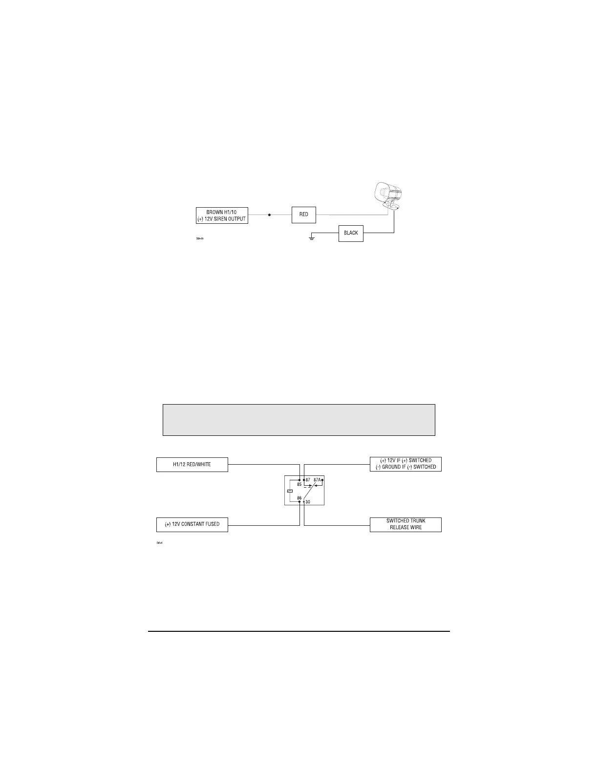
H1/10 BROWN (+) Siren Output
Connect this to the red wire of the siren. Connect the black wire of the siren to (-) chassis ground,
preferably at the same point you connected the control module’s black ground wire.
H1/11 RED (+)12V constant power input
Before connecting this wire, remove the supplied fuse. Connect to the battery positive terminal or
the constant 12V supply to the ignition switch.
NOTE: Always use a fuse within 12 inches of the point you obtain (+)12V. Do not use the 15A
fuse in the harness for this purpose. This fuse protects the module itself.
H1/12 RED/WHITE (-) 200 mA output
When the system receives the code controlling Channel 2, for longer than 1.5 seconds, the
RED/WHITE wire will supply an output as long as the transmission continues. This is often used
to operate a trunk/hatch release or other relay-driven function.
IMPORTANT! Never use this wire to drive anything but a relay or a low-current input!
The transistorized output can only supply 200 mA of current. Connecting directly to a
solenoid, motor, or other high-current device will cause it to fail.