©
2003
Directed Electronics, Inc.
9
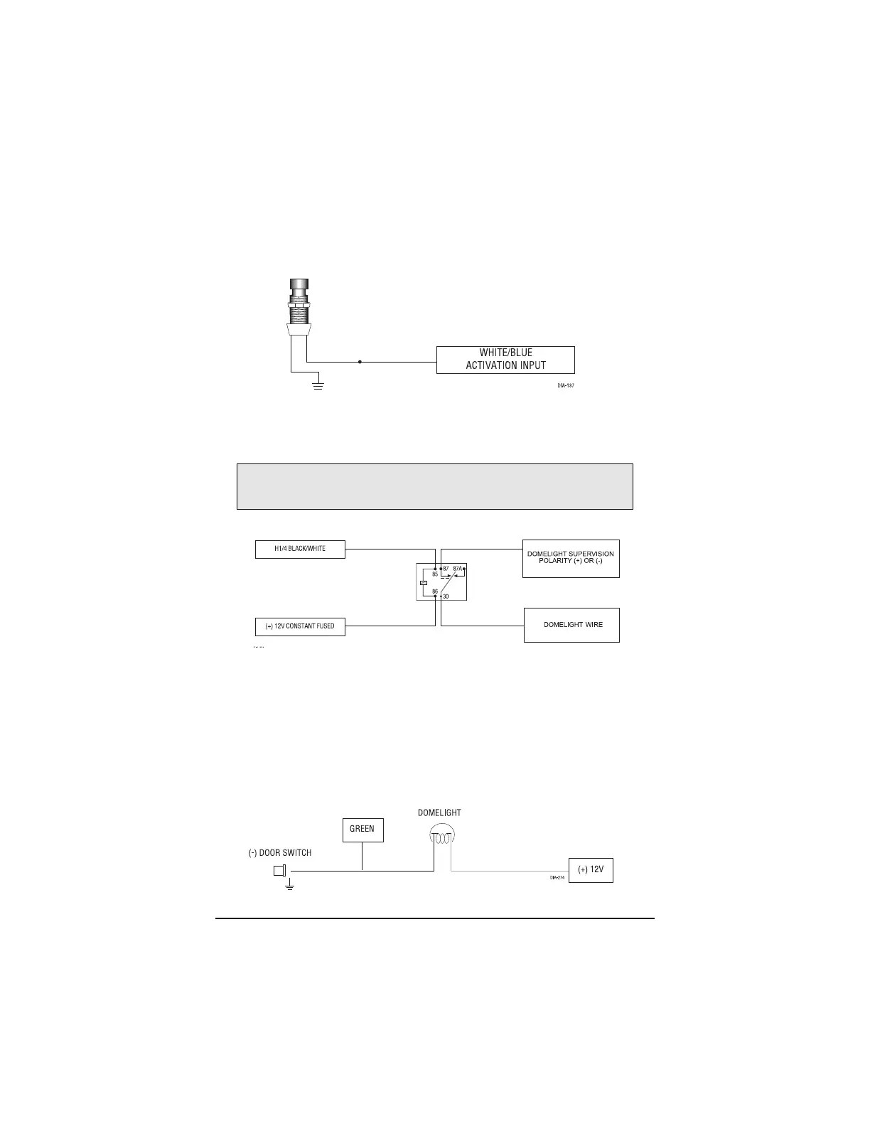
H1/3 WHITE/BLUE (-) Activation Input
A momentary input on this wire will start or stop the motor, just as transmitting Channel 3 from
the remote transmitter does. It is often connected to an optional momentary push-button switch to
make activating Valet Take Over more convenient.
H1/4 BLACK/WHITE (-) 200 mA Domelight Supervision Output
Connect this wire to the optional domelight supervision relay as shown in the following diagram:
H1/5 GREEN (-) door trigger input, zone 3
Most vehicles use negative door trigger circuits. Connect the GREEN wire to a wire showing
ground when any door is opened. When connecting to newer model vehicles there is generally a
need to use individual door triggers. See DirectFax document 1076 for wiring instructions. This
wire will report Zone 3.
NOTE: If using a door trigger wire that has a delay, Advanced Menu 2, feature 6, or the 998T
Bitwriter can be used to turn Bypass Notification off.
IMPORTANT! This output is only intended to drive a relay. It cannot be connected
directly to the domelight circuit, as the output cannot support the current draw of one
or more bulbs.