© 2004 Directed Electronics, Inc. Vista, CA
1177
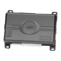
ssttaarrtteerr iinntteerrrruupptt hhaarrnneessss ((HH33)) wwiirree ccoonnnneeccttiioonn gguuiiddee
______
______
Use one of these wire as a starter interrupt input and the other as a starter interrupt output wire
NNOOTTEE::
These two black wires are interchangeable.
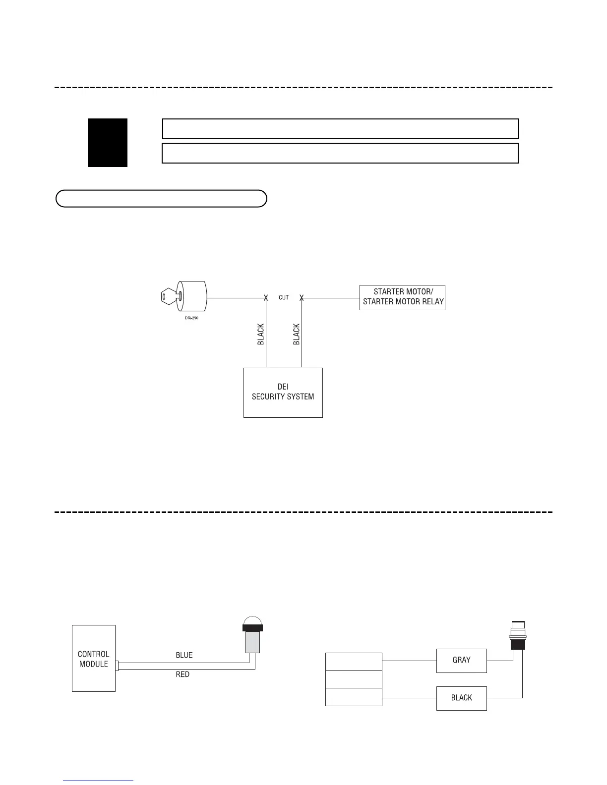
pplluugg--iinn LLEEDD aanndd vvaalleett//pprrooggrraamm sswwiittcchh
The LED and the Valet/Program switch both plug into the control module. The LED system status indicator plugs
into the white two-pin port, while the Valet
®
/Program switch should be plugged into the blue two-pin port. The
status LED and Valet
®
/Program switch each fit into
9
/32-inch holes.
LLEEDD SSyysstteemm SSttaattuuss IInnddiiccaattoorr VVaalleett
®®
//PPrrooggrraamm SSwwiittcchh
HH33//11 aanndd HH33//22 BBLLAACCKK ssttaarrtteerr iinntteerrrruupptt wwiirreess
BBLLAACCKK SSTTAARRTTEERR IINNTTEERRRRUUPPTT OOUUTTPPUUTT
BBLLAACCKK SSTTAARRTTEERR IINNTTEERRRRUUPPTT IINNPPUUTT
HH33//11
HH33//22
 Loading...