© 2004 Directed Electronics, Inc. Vista, CA
77
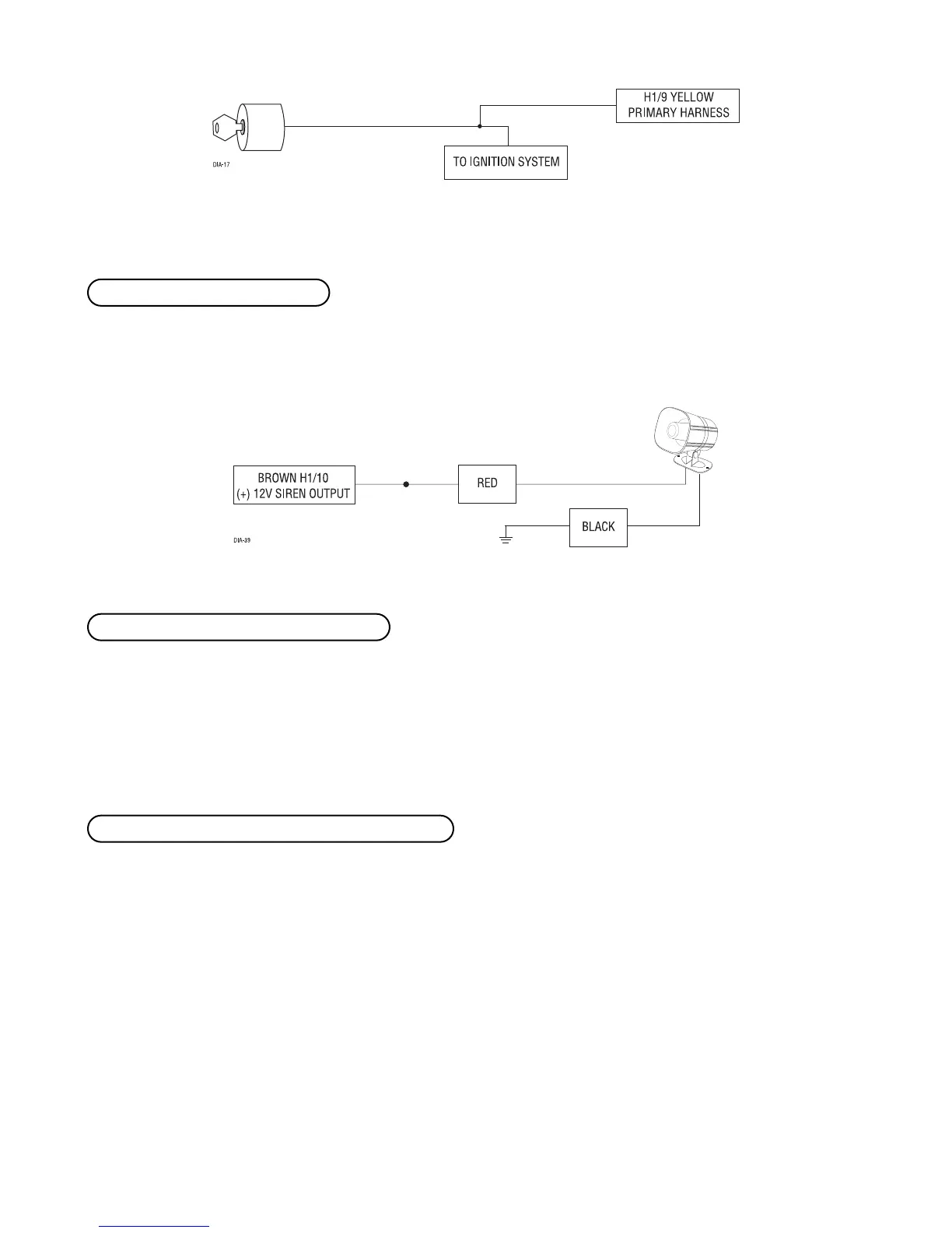
Connect this to the red wire of the siren. Connect the black wire of the siren to (-) chassis ground, preferably at
the same point you connect the control module’s black ground wire.
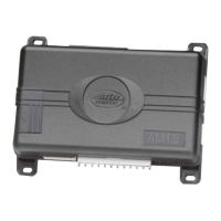
Before connecting this wire, remove the supplied fuse. Connect to the positive battery terminal or the constant
12V supply to the ignition switch.
NNOOTTEE::
Always use a fuse within 12 inches of the point you obtain (+)12V power. Do not use the
15A fuse in the harness for this purpose. This fuse protects the module itself.
When the system receives the code controlling Channel 2, for longer than 1.5 seconds, the red/white wire will
supply an output as long as the transmission continues. This is often used to operate a trunk/hatch release or
other relay-driven function.
IIMMPPOORRTTAANNTT!!
Never use this wire to drive anything but a relay or a low-current input! The tran-
sistorized output can only supply 200 mA of current. Connecting directly to a solenoid, motor,
or other high-current device will cause it to fail.
HH11//1122 RREEDD//WWHHIITTEE cchhaannnneell 22,, ((--)) 220000mmAA oouuttppuutt
HH11//1111 RREEDD ((++))1122VV ccoonnssttaanntt ppoowweerr iinnppuutt
HH11//1100 BBRROOWWNN ((++)) ssiirreenn oouuttppuutt
 Loading...