EasyManuals Logo

Directed Electronics Ready Remote User Manual

Directed Electronics Ready Remote
70 pages
To Next Page IconTo Next Page
To Previous Page IconTo Previous Page
Page #22 background imageLoading...
Page #22 background image
18
© 2006 Directed Electronics
insulation off a small portion and solder the thick ORANGE (3)
wire of the heavy gauge wire and wrap it with electrical tape.
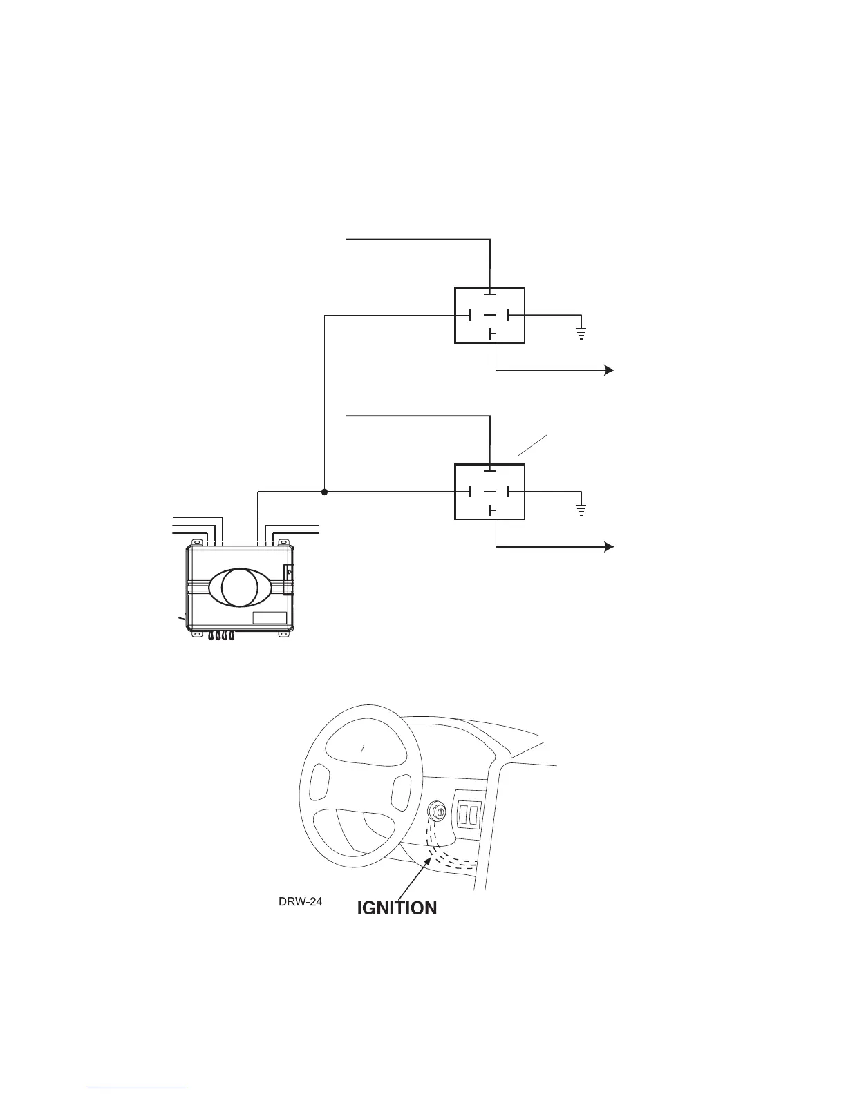
If your vehicle requires more than one accessory, an additional
relay (not provided) is required. Refer to the diagram below.
Now that the accessories have been located, find the wire
suspected to be the starter wire according to the web information
on your vehicle. Place the red lead of your LED tester on the
87
87A
86
85
30
+12 VDC CONSTANT (FUSED 20A)
GROUND
TO 2
nd
ACCESSORY
ORANGE (+) 30A OUTPUT TO
ACCESSORY CIRCUIT
TO ACCESSORY
2
nd
ACCESSORY RELAY
(NOT PROVIDED)
87
87A
86
85
30
+12 VDC CONSTANT (FUSED 20A)
GROUND
TO ACCESSORY
ACCESSORY RELAY
(NOT PROVIDED)

Questions and Answers:

Question and Answer IconNeed help?

Do you have a question about the Directed Electronics Ready Remote and is the answer not in the manual?

Directed Electronics Ready Remote Specifications

General IconGeneral
BrandDirected Electronics
ModelReady Remote
CategoryRemote Starter
LanguageEnglish

Related product manuals