9
© 2006 Directed Electronics
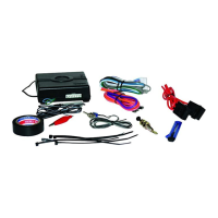
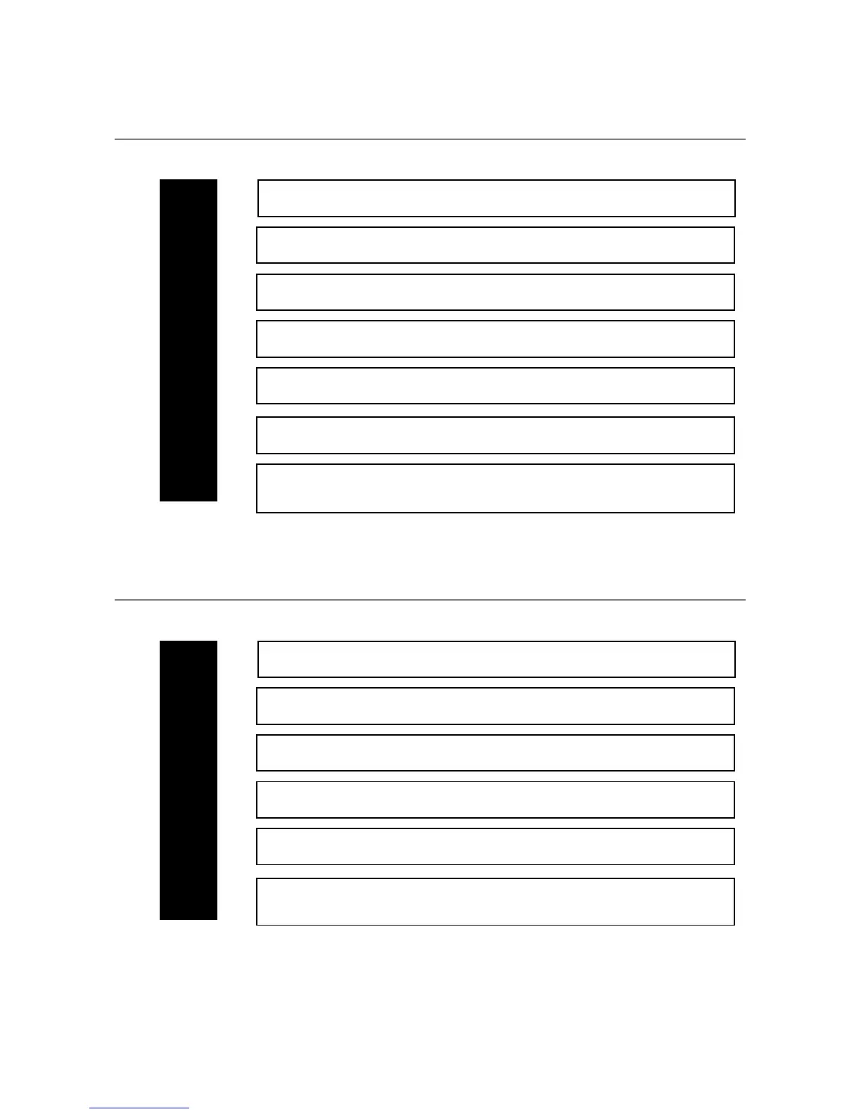
sseeccoonnddaarryy hhaarrnneessss ((HH22)),,
77--ppiinn ccoonnnneeccttoorr
___
___
___
___
___
___
___
rreellaayy hheeaavvyy ggaauuggee wwiirreess
___
___
___
___
___
___
PINK/WHITE (+) Output for 2
nd
Ignition
(not programmable)
RED (+) (30A) High Current 12V Input
PINK (+) (30A) Output to Ignition Circuit
ORANGE (+) (30A) Output to Accessory Circuit
RED (+) (30A) High Current 12V Input
VIOLET (+) (30A) Output to Starter Circuit
11
22
33
44
55
66
VIOLET Unlock #87A Normally Open (Input) looped back
to H2/4
BLUE/BLACK Unlock #30 Common Output
BROWN/BLACK UnLock #87 Normally Closed
VIOLET/BLACK Lock #87A Normally Open (Input) 15 A
GREEN/BLACK Lock #30 Common Output
WHITE/BLACK Lock #87A Normally Closed
RED/WHITE (-) Channel 2 (auxiliary channel ie: trunk)
HH22//11
HH22//22
HH22//33
HH22//44
HH22//55
HH22//66
HH22//77