EasyManuals Logo

Directed Electronics Ready Remote User Manual

Directed Electronics Ready Remote
70 pages
To Next Page IconTo Next Page
To Previous Page IconTo Previous Page
Page #17 background imageLoading...
Page #17 background image
13
© 2006 Directed Electronics
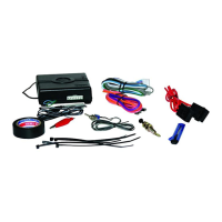
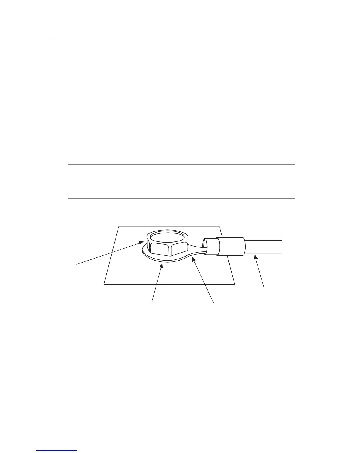
step 1
Ground Wire
The BLACK (H1/5) wire on the main 8-pin harness is ground.
First strip back a ¾-inch section of the insulation off the BLACK
wire and crimp a ring terminal (not provided) to that wire.
Locate a clean, paint-free metal surface in the drivers kick panel.
Using a self-tapping screw, drill the screw with the ring terminal
to the metal area. Once screwed down, pull on the wire to ensure
a good connection.
SELF-TAPPING
BOLT OR SCREW
RING
TERMINAL
GROUND
WIRE
NOTE: REMOVE ANY PAINT
BELOW RING CONNECTOR
DIA-591
note: More problems are attributed to poor ground con-
nections than any other cause. Take extra care to ensure
the ground is a clean metal-to-metal contact and secure.

Questions and Answers:

Question and Answer IconNeed help?

Do you have a question about the Directed Electronics Ready Remote and is the answer not in the manual?

Directed Electronics Ready Remote Specifications

General IconGeneral
BrandDirected Electronics
ModelReady Remote
CategoryRemote Starter
LanguageEnglish

Related product manuals