34
©
2005
Directed Electronics, Inc.
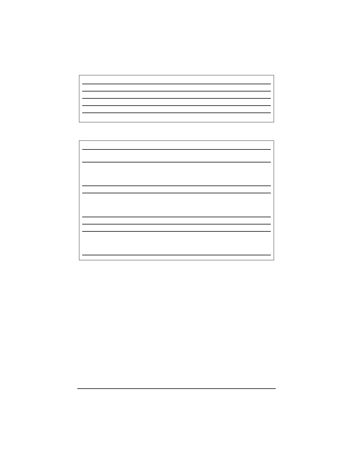
System Status Chirps
Table of Zones
NOTE: The Warn Away
®
response does not report on the LED.
Zone No. Trigger type Input description
1 Instant H1/7 BLUE wire. Connect to optional hood/trunk
pins.
2 Multiplexed For the onboard shock sensor light impacts
will trigger a Warning Zone response, while
heavy impacts will instantly trigger the full alarm
sequence.
3 Instant Two-stage, or constant Door switch circuit. H1/8 GREEN or H1/6 VIOLET.
4 Multiplexed Input Inputs shorter than 0.8 seconds will trigger a
Warning Zone response, while inputs longer than
0.8 seconds will instantly trigger the full alarm
sequence.
5 Two-stage (similar to doors) Ignition input. H1/4 YELLOW.
6 Hood trigger H2/2 GREY
7 Multiplexed input (sensors) Inputs shorter than 0.8 seconds will trigger a
Warning Zone response, while inputs longer than
0.8 seconds will instantly trigger the full alarm
sequence.
Action Number of Chirps Description
Arm 1 System armed
Arm 1 (3 second delay), 1 System armed with Bypass Notification
Disarm 2 System disarmed
Disarm 4 System disarmed with Tamper Alert
Disarm 5 System disarmed NPC
®
active